


GPS/IMU ASSEMBLY
VanLink System featuring TouchStar™ Technology - Troll Systems Corporation VanLink System Requirements
Document VLSG-01 - 10/21/08 2-7
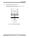
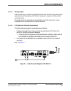
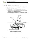
2.3.5 Typical Network Configuration for VanLink
2.3.5.1 GPS/IMU Mounting Considerations
In order for the GPS/IMU to continually provide accurate heading information a few
considerations need to be made when mounting the assembly on the roof of the vehicle.
• The GPS/IMU assembly must be mounted as far away from any significant sources
of current such as flood lights or motors as possible because it is sensitive to EMI
generated by these types of devices.
• It’s recommended that it be installed at least 24” from the pan/tilt device so as not to
be affected by the EMI generated by the DC motors.
• The GPS/IMU can be mounted either on the mast using a bracket or on the roof of
the van in an area least likely to be affected by EMI.
— If it is mounted on the mast, six (6) additional wires will be needed to be run
through the NYCOIL.
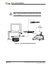
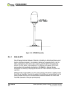
2.4 GPS/IMU ASSEMBLY
2.4.1 GPS/IMU Mounting Considerations
If the GPS/IMU (see Figure 2–4) is to provide continuously accurate heading
information. a few mounting considerations need to be made when the assembly is to
be installed onto the roof of the vehicle.
• The GPS/IMU assembly must be mounted as far away from any significant sources
of electrical current as possible such as flood lights or motors because its sensitivity
to the EMI generated by these types of devices.
— It is recommended that the GPS/IMU be installed at least 24” from the pan/tilt
device so it will not to be affected by the EMI generated by the DC motors.
• The GPS/IMU can be mounted either on the mast using a bracket or on the roof of
the van in an area least likely to be affected by EMI.
• If it is mounted on the mast, six (6) additional wires will be needed to be run through
the NYCOIL