


Digital Display Wall Clock Guide Page 6
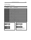
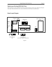
DIP Switch Settings
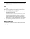
Table 1 - S1 (1-5) Secondary Clock Correction
1 2 3 4 5 Secondary Clock Selection
0=Closed 1=Open *=Factory Default
0 0 0 0 0 Stand Alone *
1 0 0 0 0 3-Wire Synchronous
0 1 0 0 0 3-Wire Minute Impulse (59
th
Minute)
1 1 0 0 0 3-Wire Minute Impulse (59
th
Minute) With 12 Hour Correction
0 0 1 0 0 Standard Electric Synchronous
1 0 1 0 0 Standard Electric AR-2A - 2-Wire Dual Voltage
0 1 1 0 0 Standard Electric AR-2 - 2-Wire Dual Voltage
1 1 1 0 0 Cincinnati D8, Honeywell ST402A, Faraday Synchronous
0 0 0 1 0 Simplex 59
th
Minute Dual Motor
1 0 0 1 0 Simplex 45
th
Minute Dual Motor
0 1 0 1 0 Edwards Dual Motor
1 1 0 1 0 Standard Electric AR-3 - 3-Wire Minute Impulse
0 0 1 1 0 National Synchronous Wired
1 0 1 1 0 Stromberg Synchronous Wired
0 1 1 1 0 Cincinnati D1
1 0 0 0 1 Cincinnati D6, Edwards 2406
0 1 0 0 1 2-Wire Impulse Alternating (24VDC)
1 1 0 0 1 Electronic Coded (3510 Hz Receiver Required)
0 0 1 0 1 Straight Frequency (3510 Hz Receiver Required)
1 0 1 0 1 3-Wire Minute Impulse (58
th
Minute)
0 1 1 0 1 3-Wire Minute Impulse (44
th
Minute)
1 1 1 0 1 2-Wire Reverse Polarity Minute Impulse (59
th
Minute)
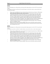
Table 2 - S1 (6-7) RS 485 Baud Rate
6 7 Baud Rate
0=Closed 1=Open
0 0 1200 Baud
1 0 2400 Baud
0 1 4800 Baud
1 1 9600 Baud *
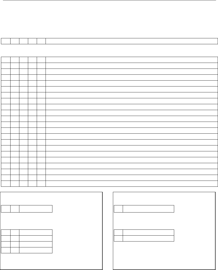
Table 3 - S1 (8) 12 / 24 Hour Display
8 12 / 24 Hour Display
0=Closed 1=Open
1 12 Hour *
0 24 Hour
Note: When switches 1-5 are set for any
secondary type other than Stand-Alone, the
display is forced to 12 Hour and the PM
indicator does not illuminate.