


DDC-TC Timer Control Panel Digital Display Wall Clock Guide Page 50
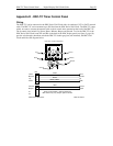
Appendix D - DDC-TC Timer Control Panel
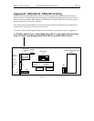
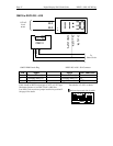
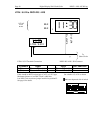
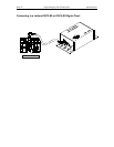
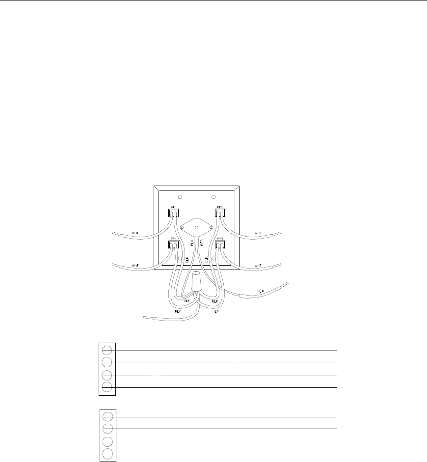
Wiring
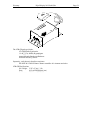
The DDC-TC can be connected to the DDC Series Wall Clock with a 6 conductor CAT3 or CAT5 network
cable. The DDC-TC can be mounted up to 200 feet from the DDC Series Wall Clock. The DDC-TC comes
with 6 wire nuts to connect the network cable to the 6 control wires mounted on the back of the DDC-TC.
The 6 control wires include Up, Down, Hours, Minutes, Beeper and Ground. To wire the DDC-TC to the
DDC Series Wall Clock locate JP2 and JP4 on the back of the DDC display panel (see figure 2, page 10),
pass the wire through a knockout at both the DDC-TC double-gang box (not included), the DDC Wall
Clock and follow the diagram below.
Beeper
Ground
Minutes
Hours
Up
Down
Rear View - Used for Reference
DDC Series Wall Clock
JP2
JP4
Ground
Beeper
Down
Up
Minutes
Hours
DDC-TC Panel
CAT3 or CAT5 Cable - 200 feet maximum
Ground
Beeper
Down
Up
Minutes
Hours
D-
D+
Green
Green / White
Brown
Blue
Blue / White
Brown / White
Wire colors may vary. Keep in pairs as shown