


Page 21 Digital Display Wall Clock Guide DDC2 / 4-RS Wiring
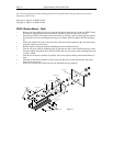
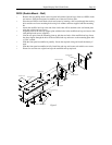
Appendix A - DDC2-RS / 4-RS Secondary Clock Wiring Diagrams
Note: See Appendix B for DDC2-RS-24 / DDC4-RS-24 wiring.
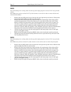
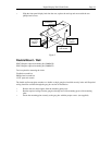
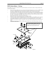
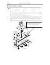
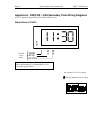
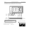
Stand-Alone (115VAC)
GRND
AC IN
AC RTN
BLK
BLK
115VAC
Local
Power
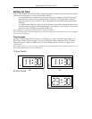
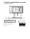
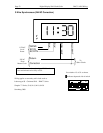
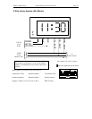
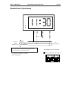
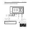
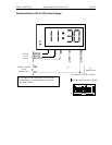
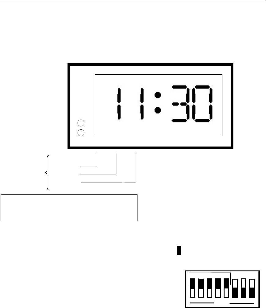
Set switches 1-5 of S1 as shown.
Indicates depressed side of switch
O
P
E
N
1
2
3
4
5
6
7
8
H
M
Hour and Minutes must be set manually. Use of a
9Volt alkaline battery is recommended to avoid
resets after power failures.