


LTRx-512 Installer’s Guide
Wiring Diagrams
33
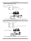
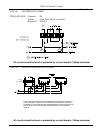
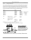
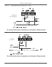
TYPE 15 - STRAIGHT FREQUENCY
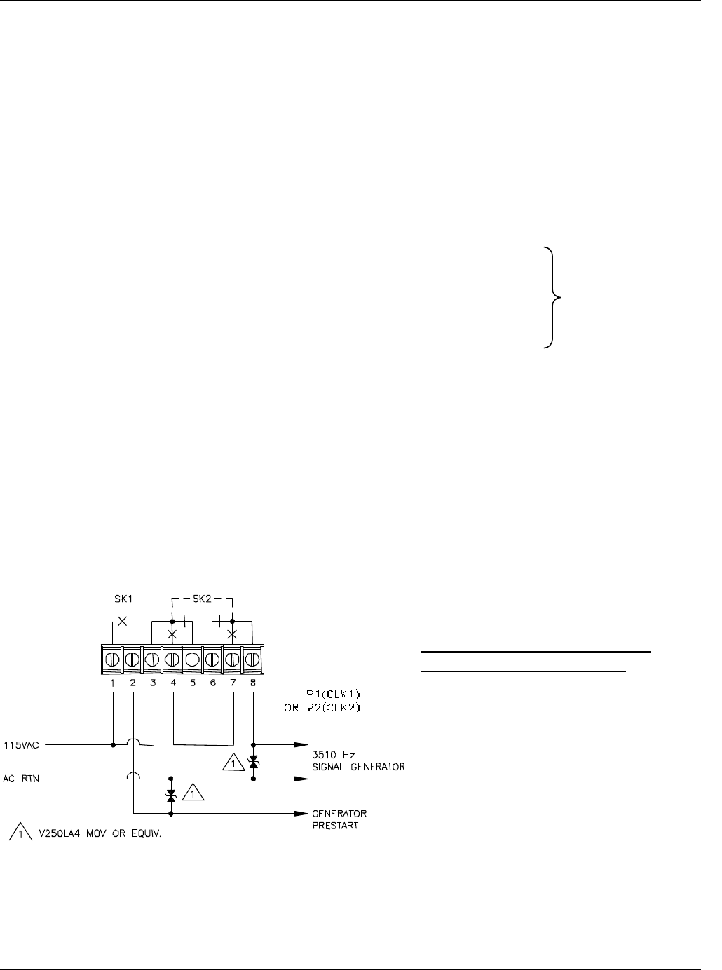
Clock correction and bell circuit operations are generated by sequentially applying various frequencies
onto the 120 VAC. Each bell and clock correction circuit has its own frequency. Each bell and clock
correction circuit has a receiver circuit that applies the associated bell or clock frequency (3510 Hz
normally used for clock signals). For daylight savings, the clocks advance to the proper time by normal
12-hour correction, not at 2:00 AM. The time sequence of applying the frequencies to the 120 VAC is
shown below, and the Master’s bell and system relays control these frequencies:
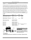
RELAY FROM TO
Bell Ckt. 1 H:MM:00 H:MM:05
Bell Ckt. 2 H:MM:05 H:MM:10
Bell Ckt. 3 H:MM:10 H:MM:15
Bell Ckt. 4 H:MM:15 H:MM:20
Bell Ckt. 5 H:MM:20 H:MM:25
Bell Ckt. 6 H:MM:25 H:MM:30
SK2 (Hourly Correction) H:57:54 H:58:02
(12-Hour Correction) 5:57:54 5:58:08
SK1 (Hourly Correction &
12-HourCorrection) H:57:00 H:59:00
(Bells) 35 sec of min 30 sec of
previous to Bell time
Bell
NOTE: Bells must be programmed 1 minute ahead of desired time.
Bells will not work during manual clock corrections and at the 58
th
minute.
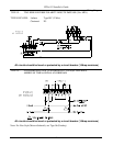
For Masters including firmware
versions prior to V2.17 only:
NOTE: The LTRx-512 was designed
to work with clocks that do not
require a generator pre-start to set the
frequency level. Clocks using this pre-
start may not work with the LTRx-
512 firmware older than V2.17.
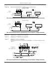
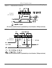
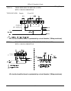
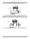
All circuits should be fused or protected by a circuit breaker (10Amp maximum)
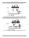
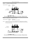
Bells should not be
scheduled for:
HH:58:SS
or
00:00:SS