


LTRx-512 Installer’s Guide
Wiring Diagrams
43
1 2
3
4
5 6
7 8
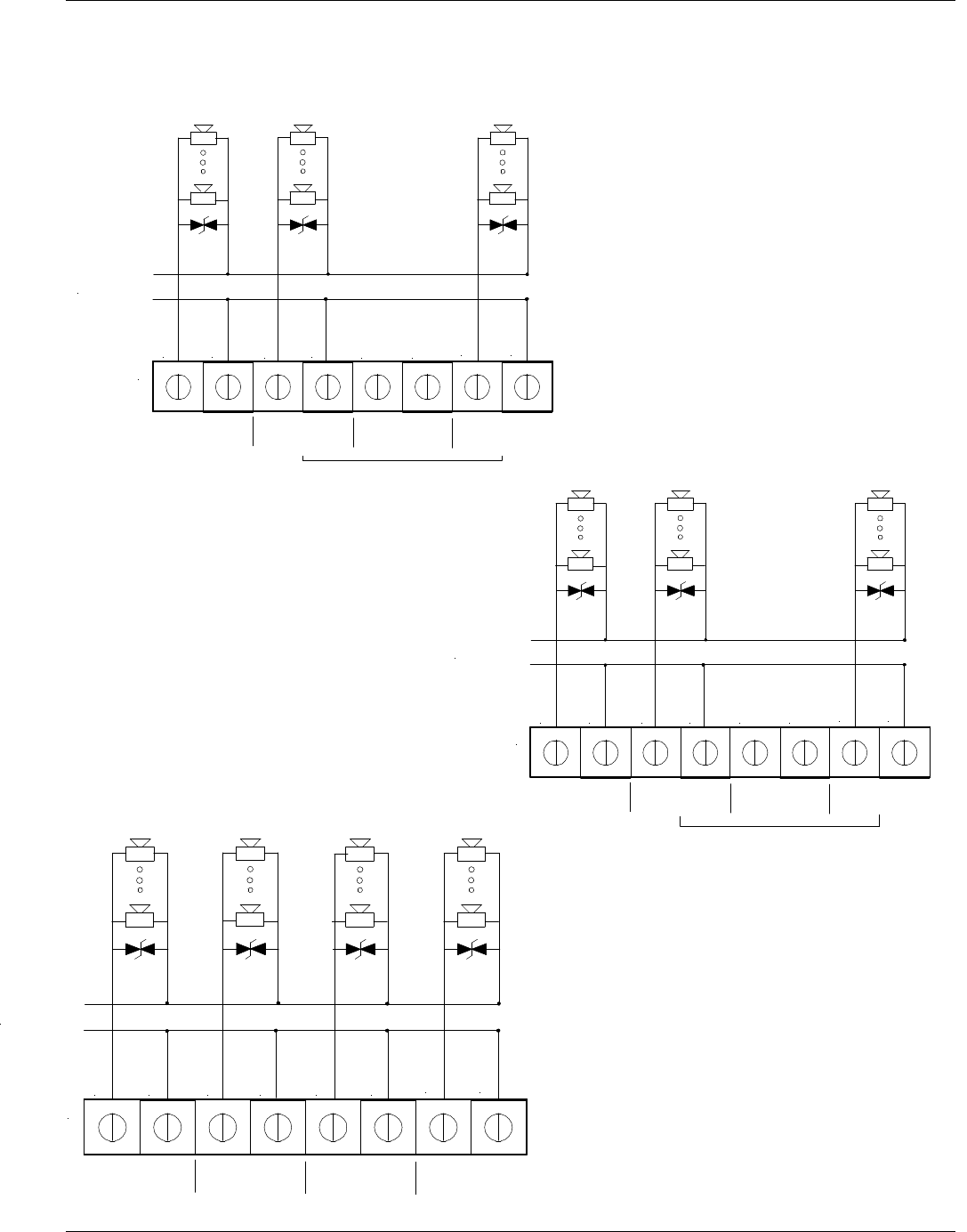
Zone 6 Zone 5A Zone 5B
P2
Voltage IN
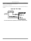
Zone 5A & 5B Operate Together
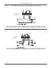
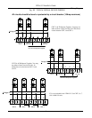
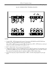
Fig. D2 - TYPICAL SIGNAL DEVICE WIRING
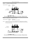
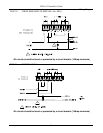
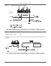
All circuits should be fused or protected by a circuit breaker (10Amp maximum)
CKT 7A & 7B Operate Together. You
may use either of these circuits for bells.
CKT 5A & 5B Operate Together. You
may use either of these circuits for
bells.
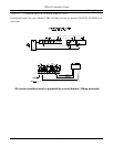
Zone 1 – 4 are not included in the LTR4-512.
Use Zones 5,6,7, & 8 for Bell Circuits.
1 2
3
4
5 6
7 8
Zone 1 Zone 2 Zone 3 Zone 4
P3
Voltage IN
1 2
3
4
5 6
7 8
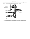
Zone 8 Zone 7A Zone 7B
P1
Voltage IN
Zone 7A & 7B Operate Together
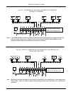
CKT 7A & 7B Operate Together. You may use
either of these circuits for bells. In LTR4, these
circuits become CKT 3 and CKT 4.
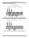
CKT 8 CKT 7A CKT 7B
CKT 7A & 7B Operate Together
CKT 5A & 5B Operate Together. You may
use either of these circuits for bells. In
LTR4, these circuits become CKT 1 and
CKT 2.
CKT 6 CKT 5A
CKT 5B
CKT 5A & 5B Operate Together
CKT 4 CKT 3 CKT 2 CKT 1
P3 is not included in the LTR4-512. Use CKT 5, 6, 7,
& 8 for Bell Circuits.