


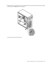
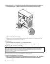
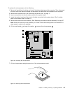
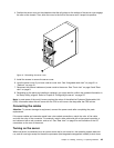

4. Position the server cover on the chassis so that the rail guides on the bottom of the server cover engage
the rails on the chassis. Then, slide the cover to the front of the server until it snaps into position.
Figure41. Reinstalling the server cover
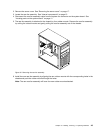
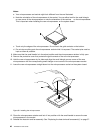
5. Install the screws to secure the server cover.
6. Lock the server cover if you have a server cover lock. See “Integrated cable lock” on page 51 or
“Padlock” on page 51.
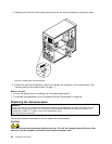
7. Reconnect the external cables and power cords to the server. See “Front view” on page 9 and “Rear
view” on page 9
.
8. Depending on the parts you installed or replaced, you might need to conrm the updated information in
the Setup Utility program. Refer to Chapter 6 “Conguring the server” on page 53
.
Note: In most areas of the world, Lenovo requires the return of the defective Customer Replaceable Unit
(CRU). Information about this will come with the CRU or will come a few days after the CRU arrives.
Connecting the cables
Attention: To prevent damage to equipment, connect the power cords after completing the parts
replacement.
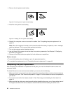
If the server cables and connector panel have color-coded connections, match the color of the cable
end with the color of the connector. For example, match a blue cable end with a blue panel connector, a
red cable end with a red connector, and so on. See “Rear view” on page 9
for an illustration of the I/O
connectors on the rear of the server.
Turning on the server
When the server is connected to an ac power source but is not turned on, the operating system does not
run, and all core logic except for the service processor (the integrated management module) is shut down;
Chapter 5. Installing, removing, or replacing hardware 49