


Chapter 4. BUFFER MEMORY CONFIGURATION AND FUNCTIONS
4- 2
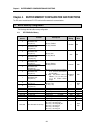
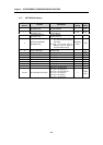
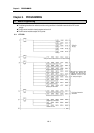
4.1.2 K4F-PIDA Buffer Memory
Address
(Decimal)
Function Descriptions
Default
Setting
Read /
Write
0
Loop enable/disable
Specification area
Bit On(1): Enabled
Bit Off(0): Disabled
Disabled
R/W
1
Auto/Manual operation
Specification area
Bit On(1): Auto
Bit Off(0): Manual
Auto
R/W
2
Forward/Reverse action
Specification area
Bit On(1): Reverse
Bit Off(0): Forward
Forward
R/W
3
SET data enable/disable
Specification area
Bit On(1) : Set each content of address
0, 2, 5 to 12, and 21 to 52 to a
new setting.
Bit Off(0) : The previous values of
address 0, 2, 5 to 12, and 21 to
52 remains without change.
No Setting
Values
R/W
4 Loop run information
Bit On(1) : Run
Bit Off(0) : Stop
Read
Only
5 to 12 SV of each loop Setting range : 0 to 16000 “0”
R/W
13 to 20 PV of each loop Input range : 0 to 16000 “0”
R/W
21 to 28 M_MV of each loop Setting range : 0 to 16000 “0”
R/W
29 to 36 P of each loop Setting range : 0 to 10000 “500”
R/W
37 to 44 I of each loop Setting range : 0 to 30000 “1000”
R/W
45 to 52 D of each loop Setting range : 0 to 30000 “0”
R/W
53 to 60 MV of each loop Output range : 0 to 16000
Read
61 to 68 Error information of each loop
Bit 0 On(1) : out-of-range SV
Bit 1 On(1) : out-of-range PV
Bit 2 On(1) : out-of-range M_MV
Bit 3 On(1) : out-of-range P
Bit 4 On(1) : out-of-range I
Bit 5 On(1) : out-of-range D
Read
Only