


Chapter 5. DEDICATED INSTRUCTIONS FOR SPECIAL MODULES
5 - 2
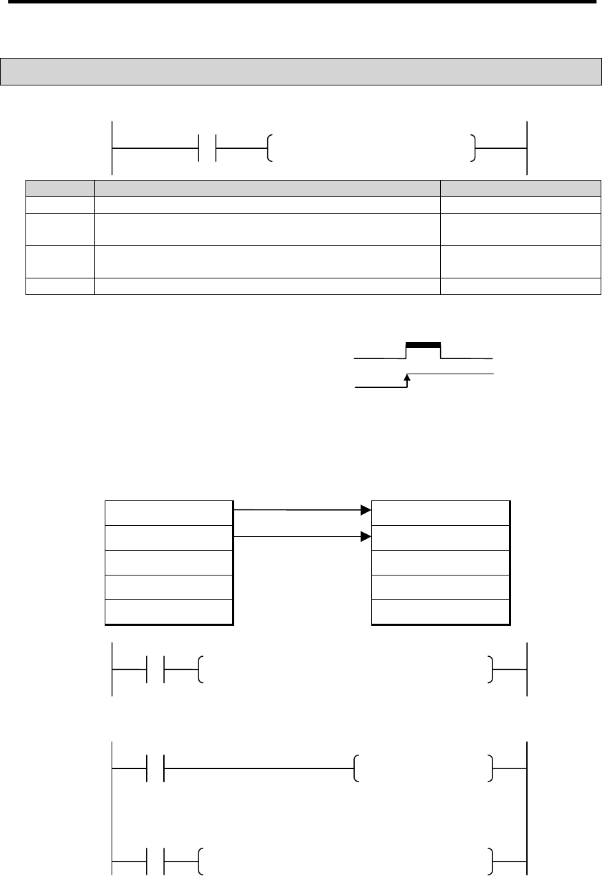
5.2 Write to Buffer Memory
⋅
⋅⋅
⋅
⋅
⋅⋅
⋅
⋅
⋅⋅
⋅
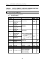
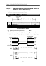
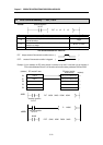
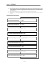
PUT, PUTP
<Format> execution condition
for PUT
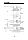
Format Descriptions Available Data Type
n1 The slot No. where a special module is mounted. Integer
n2
Head address of the special module buffer memories to which the
data will be written..
Integer
D
Head address of the device where the data to be written has been
stored, or an integer
M,P,K,L,T,C,D,#D
n3 Number of data to be written. Integer
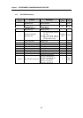
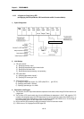
<The difference between PUT and PUTP>
PUT: always executed if the execution condition turns on. ( )
PUTP : executed if the execution condition is triggered. ( )
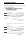
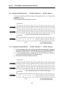
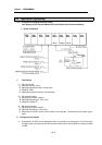
Example 1) In this example, the PID control module is mounted on the slot 6 in the base unit and the data of
CPU module addresses D0 and D1 will be written to the buffer memory addresses D202 and D203.
(address) CPU module D area PID control module
buffer memory (address)
D0 Data 0 Specify the enabled loop 0
D1 Data 1 Specify the enabled loop 1
D2 2
D3 3
D2 4
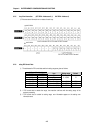
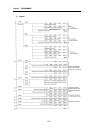
<PUT>
execution condition
for PUT
execution condition
<PUTP> for PUTP
M0000
PUT n1 n2 S n3
PUT 00006 00000 D0000 00002
D M0000
PUTP 00006 00202 D0000 00002