


Chapter 6. PROGRAMMING
10 - 6
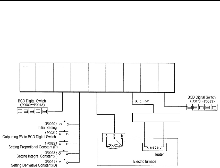
10.2.2 A Program for Control Using a RTD
(with Applying the RTD Input Module, PID Control Module and D/A Conversion Module)
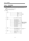
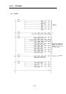
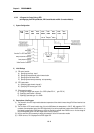
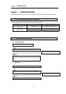
1) System Configuration
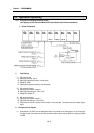
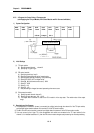
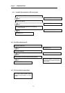
2) Initial Settings
(1) PID control module
A) Specifying used loop : loop 0
B) Specifying forward/reverse action: forward action
C) Specifying the Set Value: 8000
D) Specifying auto/manual processing : auto processing
(2) RTD input module
A) Specifying used channel: channel 0
B) Specifying RTD sensor type: Pt100
(3) D/A conversion module
A) Setting the voltage input range to –5 to 5 DCV (offset: DC 1V, gain: DC 3V)
B) Specifying used channel : channel 0
C) Specifying input data type : 0 to 16000
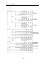
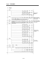
3) Descriptions of the Program
(1) The channel 0 of the RTD input module detects a temperature of the electric furnace through Pt100 and receives it as
a digital value.
(2) The Set Value of PID control module loop 0 is set to 8000(where the temperature is 100°C). With regards to P.I.D
constants, the manipulated value in the BCD digital switch is set to the proportional constant when P0022 turns on, to
the integral constant when P0023 turns on, and to the Derivative constant when P0023 turns on. As the change of
MV, the manipulated value in the BCD digital switch is set to a new MV.
(3) MV, the result from PID processing is output at the channel 0 of the D/A conversion module.
(4) If P0021 turns on, PV is displayed on the BCD digital LED.
Power conversion device
RTD
K7F-
AD4A
Ch. 0
K7F-
PIDA
Loop 0
K7F-
RD3A
Ch. 0
K7X-
210S
K7X-
310S
K7P-
30AS
K7S-
122S
K7S-
132S
K7Y-
301S