


Power and Control Wiring
13
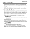
5.5 Remote Source Selection Wiring
An optional Remote Source Selection board may be installed in your Liebert STS2. This board is
installed in the same bay as the communications options. See Figures 21 and 22 for the location of
these options. See Figure 23 for information on the control wiring for the Remote Source Selection
option.
The Remote Source Selection allows you choose the preferred input source from a remote location.
Terminal connections allow the customer to remotely select a source to be the preferred source in the
same process as the local source transfer selection.
The unit’s preferred source selection and Remote Source Selection are active at the same time, with
the Liebert STS2 following the last request for a preferred source change, regardless of whether it
was from the local or Remote Source Selection controls.
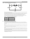
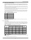
A six pin terminal block provides the Remote Source Selection connections. Two pairs of wires are
used from the switch to trigger the source selection. You can select the type of switch used for this
remote control. Connections are made to four of the connections, using Form A dry contacts. The
contacts are numbered left to right:
See 10.3 - Enabling Remote Source Selection for instructions on enabling the Remote Source
Selection option.
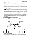
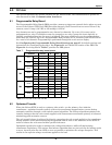
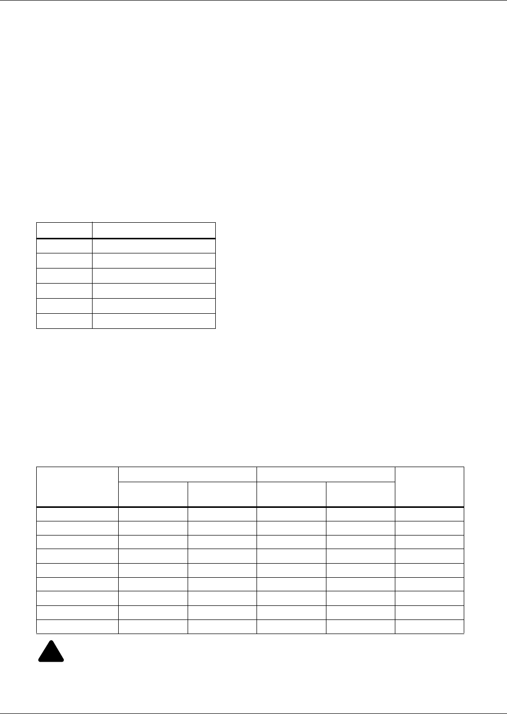
5.6 Power Supply
The Liebert STS2 is supplied with redundant power supplies that are designed to operate from a
voltage range of 200V to 600V. The unit is set at the factory to match the nameplate voltage. Field
adjustments are not necessary. If the unit needs to operate at a voltage other than what is listed on
the nameplate, contact Liebert Services or your local Emerson representative. Table 6 provides
transformer tap information.
Table 5 Remote source selection terminal block
Contact Connection
1 Source 1
2 Isolated ground
3 Source 2
4 Isolated Ground
5 DO NOT USE
6 DO NOT USE
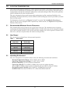
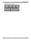
Table 6 Terminal block 1 and terminal block 2 wire connections
Voltage
Connect t Connect
Jumper
Between
F1
TB1-XX
F2
TB1-YY
F3
TB2-XX
F4
TB2-YY
200 1 9 1 9 1-7
208 1 10 1 10 1-7
220 2 12 2 12 6-8
240 1 11 1 11 1-7
380 1 8 1 8 2-7
400 1 9 1 9 3-7
415 1 10 1 10 4-7
480 1 11 1 11 5-7
600 1 12 1 12 6-7
!
CAUTION
Using Table 6, ensure that the wiring for the control transformers matches the input voltage
for the unit.
Improper wiring could result in blown fuses.