


5
LEARNING TO WELD
5
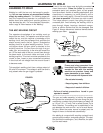
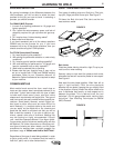
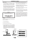
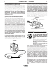
Penetration
Unless a weld penetrates close to 100% of the metal
thickness, a butt joint will be weaker than the material
welded together. In the example shown in Figure 7,
the total weld is only half the thickness of the material
thus the weld is only approximately half as strong as
the metal.
FIGURE 7
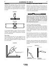
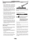
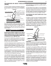
FIGURE 8
In the example shown in Figure 8, the joint has been
welded so that 100% penetration could be achieved.
The weld, if properly made, is as strong as or stronger
than the original metal.
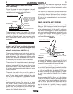
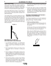
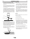
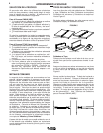
Fillet Joints
When welding fillet joints, it is very important to hold
the wire electrode at a 45° angle between the two
sides or the metal will not distribute itself evenly. The
gun nozzle is generally formed at an angle to facilitate
this. See Figure 9.
FIGURE 9
Welding In The Vertical Position
Welding in the vertical position can be done either ver-
tical-up or vertical-down. Vertical-up is used whenever
a larger, stronger weld is desired 1/4”(6.4mm) and
thicker material. Vertical-down is used primarily on
sheet metal 3/16”(4.8mm)and thinner materials cause
for fast, low penetrating welds.
Use of this unit on thicker materials than recom-
mended may result in welds of poor quality. The
welds may appear to be fine, but may lack the
fusion or bonding necessary to give a strong
weld. This is called "Cold Casting" or "cold lap-
ping" and is some what similar to a cold solder
joint. Weld failure may result.
------------------------------------------------------------------------
Vertical-up And Overhead Welding
The problem, when welding vertical-up 1/4”(6.4mm)
and thicker material, is to put the molten metal where
it is wanted and make it stay there. If too much molten
metal is deposited, gravity will pull it down wards and
make it “drip”. Therefore, a certain technique has to
be followed.
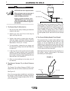
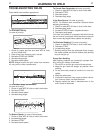
When welding out-of-position, run stringer beads.
Don’t whip, break the arc, move out of the puddle, or
move too fast in any direction. Use Wire Feed Speed
(WFS) in the low portion of the range. The general
technique and proper gun angle is illustrated in Figure
10.
Generally, keep the electrode nearly perpendicular to
the joint as illustrated. The maximum angle above per-
pendicular may be required if porosity becomes a
problem.
FIGURE 10
45¡ CENTER LINE
TO HORIZONTAL PLATE
WARNING
PROPER GUN ANGLE
FOR GMAW PROCESS
WELDING IN THE VERTICAL DOWN POSITION
3/16 INCH AND THINNER
1/4 INCH AND THICKER
PROPER GUN ANGLE
FOR FCAW PROCESS
WELDING IN THE VERTICAL UP POSITION
45° CENTERLINE OF GUN TO
HORIZONTAL PLATE