


LINDY CPU Switch Dual Junior Installation and Use Page 38
4. Using the LINDY CPU Switch Dual Junior
This section explains the general operation of the LINDY CPU Switch Dual Junior.
We recommend that you read this section before starting to use the product.
4.1 Rear panel special function switches
Before powering on the LINDY CPU Switch ensure that the two option switches on
the rear are set to the OFF (up) position. Option switch 1 is reserved for future use
and option switch 2 is used to enable firmware upgrades (see section 5).
4.2 Power supply connections and indicators
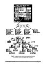
Plug the power adapter into the power inlet. The power indicator on the front of the
LINDY CPU Switch (see figure 1) monitors the voltage that is being supplied to the
power inlet. If the power indicator is illuminated then a healthy power adapter is
connected.
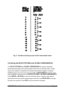
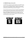
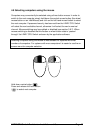
4.3 USER display and key switch
The USER key selects the user port that is shown on the green USER display (see
figure 1). Pressing the key will cause the green display to change to the next user
port in numerical sequence. When the USER display is changed, the red
COMPUTER display will also change to show the current connection status of the
new user port. LINDY CPU Switch Dual Junior models have 2 user ports.