


10
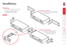
Power control port
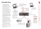
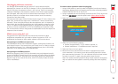
The CPU IP provides a serial port for connection to one or more optional power
control units. This allows you to control the mains power being supplied to the
connected host(s) so that an authorised remote user can, if necessary, perform a
complete cold reboot on a failed host system.
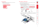
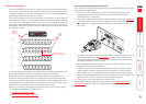
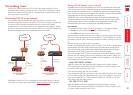
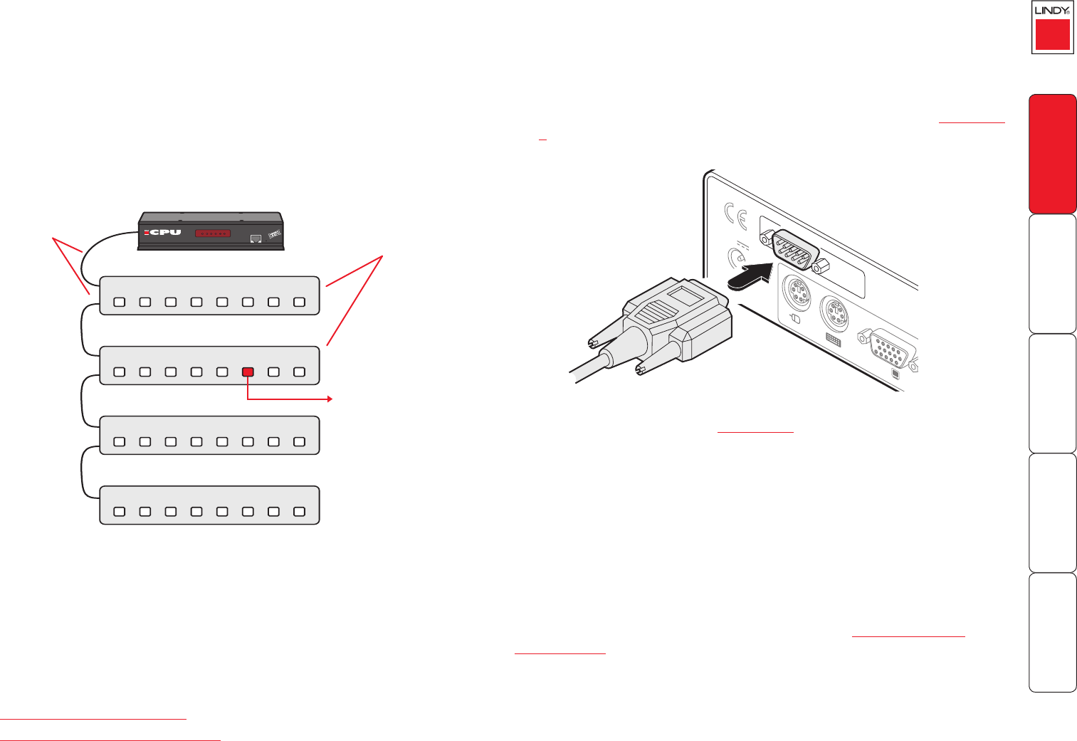
The control connector of the rst power switch is connected, via serial cable, to
the rear panel of the CPU IP. Any additional power switches are then connected
via a ‘daisy-chain’ arrangement to the rst power switch. Each power switch box
is then given a unique address and access to each power port (4 or 8 ports on
each power switch box) is gained using a combination of the switch box address
and the port number.
COM1
MODE
M
COM2
POWER
CONTROL
INDOOR
USE
ONL
Y
KVM
CONSOLE
5V
1
2
ON
2.5A
COMPUTER
/
KVM
SWITCH
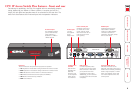
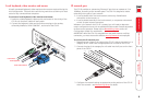
To connect and address the switch boxes
Note: The CPU IP can be powered on during this procedure, however, the switch
boxes should be switched off.
1 Mount up to four switch boxes in positions where they are close to the
computers that they will control and not too distant from the CPU IP
(preferably within 2.5 metres).
2 Use a serial cable with an RJ10 and a 9-pin D-type connector (see Appendix
7 for specication). Connect the RJ10 plug to the socket marked ‘IN’ on the
rst switch box. Connect the other end to the socket marked ‘COM2’ on
the CPU IP.
8
IN
IN
IN
IN
OUT
OUT
OUT
8
8
8
7
7
7
7
6
6
6
6
5
5
5
5
4
4
4
4
3
3
3
3
2
2
2
2
1
1
1
1
LOCREMVNC100LNKPWR
IP
Access Switch Plus
Power to computer
Box 2, port 6 - address: 26
Box 1
Box 2
Box 3
Box 4
Power
switch
boxes
‘Daisy-chain’
control
connections
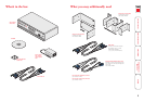
The power ports are connected to the power inputs of each computer and the
power switch box(es) are then connected to a mains power supply.
IMPORTANT: Power switching devices have a maximum current rating. It is
essential to ensure that the total current drawn by the equipment connected
to the power switching device does not exceed the current rating of the power
switching device. You must also ensure that the current drawn from any mains
socket does not exceed the current rating of the mains socket.
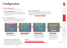
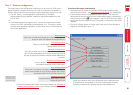
Setting up, conguring and using power switching requires three main steps:
• Connect and address the switch boxes
ð
• Congure the power strings
• Operate remote power switching
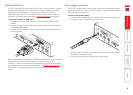
3 For each of the remaining switch boxes (if used), use a serial cable with RJ10
connectors at both ends (see Appendix 7 for specication). Connect one
end to the socket marked ‘OUT’ of the previous box and the other end to
the socket marked ‘IN’ of the next box.
4 Set the addressing switches on each switch box using the micro switches
according to the switch box manual.
5 Connect IEC to IEC power leads between each port and the power input
socket of each computer that requires power switching. Carefully note to
which power ports, on which boxes, each computer is connected. If server
systems have multiple power inputs, then each input must be connected via
separate ports, which can be on the same, or different boxes.
6 Connect each box to a suitable mains power input.
Now proceed to the conguration stage covered in the Power switching
conguration section within the Conguration chapter.