


20
Power switching conguration
Power switch conguration comprises two main steps:
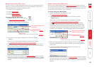
• Congure the COM2 serial port to the same speed as used by the power
switch box(es) - see Serial port conguration for details.
• Congure power ON and OFF strings for each relevant host computer.
For each power port there needs to be a valid ‘Power ON string’ and similarly an
appropriate ‘Power OFF string’. In each case, the strings are a short sequence of
characters that combine a box address, a port number, a power on or off value
and nally a checksum number so that the power unit can guard against data
errors.
If a particular computer has more than one power input (and thus requires an
equivalent number of power ports to control them), collections of strings can be
combined to switch all of the required ports together as a group.
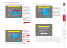
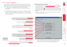
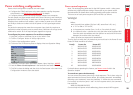
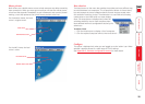
To congure the power sequences for each host computer
1 Using VNC viewer or a browser, log on as the ‘admin’ user.
2 Click the ‘Congure’ button in the top right corner.
3 Click the ‘Host conguration’ option.
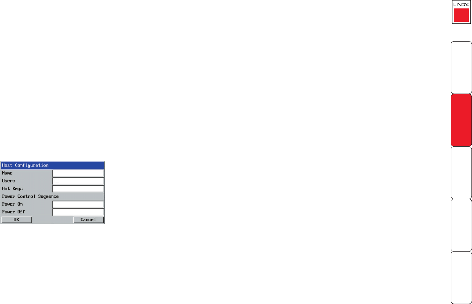
4 Click one of the 32 host entry slots to display a Host conguration dialog:
Power control sequences
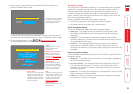
Note: The settings given below are for the LINDY power switch - other power
switches may require different settings. Please refer to your power switch
documentation for details about codes required by other power switches.
The structure of each power sequence (OFF and ON) is as follows:
\w\x\y\z
Where:
w is the switch box address (rst box is 80, second box is 81, etc.),
x is ‘31’ for ON or ‘32’ for OFF,
y is the power port number (from 1 to 8, or 9 to switch all ports),
z is a checksum value - calculate this using the other values (subtract 80H
from the switch box address and then perform an exclusive OR function
between this and the other two values).
Note: All values are expressed in hexadecimal.
Thus for the rst switch box, the codes that you would use in the Power On and
Power Off elds would be as follows:
Port(s) Power On Power Off
1 \80\31\01\30 \80\32\01\33
2 \80\31\02\33 \80\32\02\30
3 \80\31\03\32 \80\32\03\31
4 \80\31\04\35 \80\32\04\36
5 \80\31\05\34 \80\32\05\37
6 \80\31\06\37 \80\32\06\34
7 \80\31\07\36 \80\32\07\35
8 \80\31\08\39 \80\32\08\3A
All \80\31\09\38 \80\32\09\3B
For details about operating this feature, see Power control within the
Operation chapter.
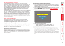
To control two ports simultaneously
You can control two power ports using a single sequence. This is done using the
same command structure as shown above, plus a delay command. Immediately
following a port command, insert the characters ‘\*’ before the next command.
For instance, to switch on ports 1 and 2 in the rst power switch, the command
line would be:
\80\31\01\30\*\80\31\02\33
For more help with power switch addressing, please contact LINDY support.
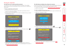
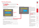
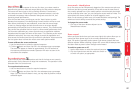
5 If necessary, congure other parameters (Name, Users, Hot Keys - MORE).
6 Enter the Power control sequences in the Power On and Power Off elds
ð
7 Click OK to close the dialog and then click the Save button in the main Host
Conguration window to store the details.