


21
Chapter 2:
SFE2000/SFE2000P Gigabit Ethernet Switch Reference Guide
Chapter
2
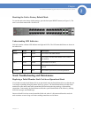
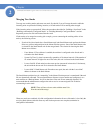
Resetting the Unit to Factory Default Mode
To reset the unit to the factory default settings, press the front panel RESET button (see Figure 3.) The
unit is set to Stack mode with a Unit ID of 0.
Understanding LED Indicators
Each unit contains a Master LED indicator and eight unit LEDs. The LED status definitions are shown in
the table below.
Stack Troubleshooting and Maintenance
Replacing a Failed Member Stack Unit in an Operational Stack
If a unit that is not the Stack Master fails in an operational stack, the Stack Master discovers that the unit
is no longer responding during the Master Discovery process. The Stack Master directs all other stack
members to route unit-to-unit traffic around the failed unit using the ring topology of the stacking
connections. Concurrently, the Stack Master notifies the system administrator of the failure by sending
SYSLOG messages and SNMP traps.
Because all traffic has been routed around the failed unit, when it is disconnected from the stack, the
stack continues to run as long as all other stacking connections are left intact.
LED Mode Color Description
Master Solid Green The switch is the Stack Master.
Off N/A The switch is not the Stack Master or the switch is
not stacked.
ID n Solid Green The switch is Unit ID n.
Off N/A The switch is not Unit ID n or the switch is not
stacked.
All ports Solid Red The switch is powered on, but not operational.