


Detailed Installation Procedure 1-3
Copyright © 2002 - 2005 by LSI Logic Corporation. All rights reserved.
1.3 Detailed Installation Procedure
This section provides step-by-step instructions for installing the host
adapter. If you are experienced in these tasks, you may prefer to use
Section 1.2, “Quick Installation Procedure.”
1.3.1 Before You Start
Before starting, look through the following task list to get an overall idea of
the steps you will perform. If you are not confident you can perform the
tasks as described here, LSI Logic recommends getting assistance.
Each FC host adapter channel that you install can act as a host for up
to 126 Arbitrated Loop FC devices, not including the adapter itself. Follow
the detailed instructions in Section 1.3.2, “Installing the Host Adapter,”
to install your host adapter board successfully.
1.3.2 Installing the Host Adapter
For safe and proper installation, refer to the user’s manual supplied with
your computer and perform the following steps to install the host adapter.
Step 1. Ground yourself before removing this host adapter board.
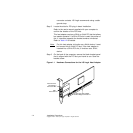
Step 2. Remove the host adapter from the packaging and check that it
is not damaged.
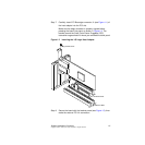
Figure 1.1 illustrates an example of this host adapter board.
Also refer to Chapter 2, “2 Gbit/s FC Host Adapter
Characteristics,” to see more detailed drawings of the 2 Gbit/s
host adapter boards.
Step 3. Switch off the computer and unplug the power cords for all
components in your system.
Step 4. Remove the cover from your computer according to the
instructions in the user’s manual for your system, to access the
PCI slots.
Caution: Ground yourself by touching a metal surface before
removing the cabinet top. Static charges on your body can
damage electronic components. Handle plug-in boards by
the edge; do not touch board components or gold