


Physical Characteristics 2-19
Copyright © 2002 - 2005 by LSI Logic Corporation. All rights reserved.
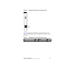
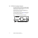
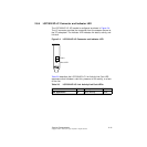
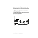
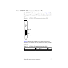
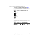
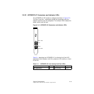
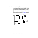
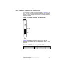
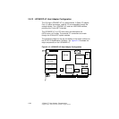
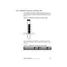
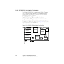
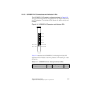
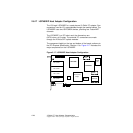
2.8.10 LSI7202EP-LC Connectors and Indicator LEDs
The LSI7202EP-LC I/O bracket is configured as shown in Figure 2.10.
The Port 0 and Port 1 connectors provide the connections from the
adapter channels to the FC subsystem. The indicator LEDs indicate link
status, activity, and link fault.
Figure 2.10 LSI7202EP-LC Connectors and Indicator LEDs
Table 2.11 describes the LSI7202EP-LC Link Activity/Link Fault LED
appearance that indicates a valid link, presence of link activity, or a fault
on the link.
Table 2.11 LSI7202EP-LC Link Activity/Link Fault LEDs
Link Activity Fault
LED Appearance Off Green Blinking Yellow
Port 0
Port 0 LED
Port 1
Port 1 LED