


1-4 Installation Procedures
Copyright © 2002 - 2005 by LSI Logic Corporation. All rights reserved.
connector contacts. LSI Logic recommends using a static
ground strap.
Step 5. Locate the slots for PCI plug-in board installation.
Refer to the user’s manual supplied with your computer to
confirm the location of the PCI slots.
This host adapter requires a 32-bit or 64-bit PCI slot that allows
bus master operation. If a 32-bit PCI slot is used, the portion of
the J1 connector opposite the bracket remains uninserted.
Refer to Table 1.2 for details.
Note: For this host adapter to function as a 64-bit device, it must
be inserted into a 64-bit PCI slot. If the host adapter is
inserted into a 32-bit PCI slot, it functions as a 32-bit
device.
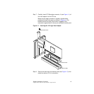
Step 6. On the back of the computer, remove the blank bracket panel
that is aligned with the PCI slot you intend to use. Save the
bracket screw.
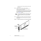
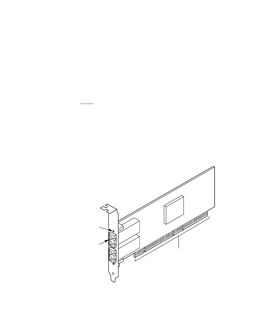
Figure 1.1 Hardware Connections for the LSI Logic Host Adapter
SFP
Transceiver
Fibre Channel
Link Activity/
Link Fault LED
PCI Bus Edge Connector J1
LSI Logic Host Adapter