


Network Configuration Examples
SP Switch Router Adapter Guide - 1.4 Update 2 C-3
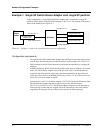
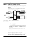
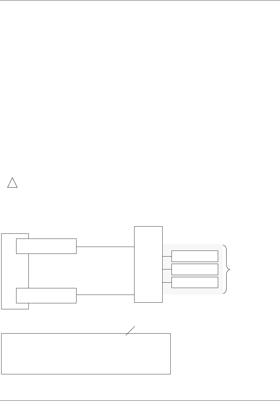
Example 2: Multiple cards, single partition
This network configuration divides the traffic for an SP processor node partition between two
or more SP Switch Router Adapter cards and achieves some load leveling among the SP
processor nodes. It provides dual, not truly redundant, connections to the router in case of SP
Switch Router Adapter card failure.
For this type of configuration, you must divide the router side of the IP network into logical
subnets and assign each SP Switch Router Adapter card to a different subnet. This logical
subnetting is required only on the router, the SP Switch viewpoint sees a single network.
Configuration requirements
• As configured in example 2, each SP Switch Router Adapter card is an active node on a
different subnet, each card interface is a subnet.
• Each card must have a unique IP address. An alias IP address cannot be used on two active
cards on the same router system.
• Enable ARP on the SP Switch network to allow assignment of alias IP addresses as part of
the recovery procedure described later in this section.
• On the router, netmasks are used to create different subnets when multiple SP Switch
Router Adapter cards are connected to the same network.
!
Warning: Be careful that the subnet mask does not, in effect, create a single subnet.
If Card 1 (gt010) is assigned the 255.255.255.0 netmask, then, for routing, both SP
Switch Router Adapter cards would be on a single subnet. This type of configuration does
not work. Each SP Switch Router Adapter card in a single router must be configured on a
different subnet.
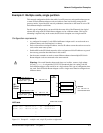
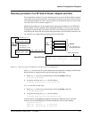
Figure C-2. Example 2 – multiple card, single SP partition configuration
net 198.174.11.0
SP Switch Router
Adapter card 1 - gt010
mask 255.255.255.128
mask 255.255.255.0
net 198.174.11.0
Partition
SP Switch Router
Adapter card 2 - gt020
net 198.174.11.128
mask 255.255.255.128
SP
Switch
Router
ARP table
card 198.174.11.1
card 198.174.11.129
SP processor node
SP processor node
SP processor node
SP
Switch
2
3
1
4
5
gt010 (0): 198.174.11.1 at 0:0:0:0:0:1
gt020 (0): 198.174.11.129 at 0:0:0:0:0:2
•
•
•
Switch node number