


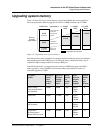
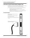

Introduction to the SP Switch Router Adapter card
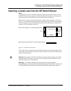
SP Switch Router Adapter card LEDs
SP Switch Router Adapter Guide - 1.4 Update 2 October 22, 1999 1-9
SP Switch Router Adapter card LEDs
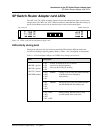
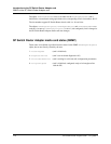
The “RX” and “TX” LEDs are under software control and indicate port states on receive and
transmit sides. The “MD” and “SW” LEDs are hardware-controlled and reflect data activity on
the SP Switch Router switch core or interface side of receive and transmit ports.
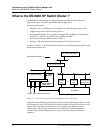
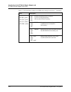
Figure 1-4. LEDs on the SP Switch Router Adapter card
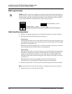
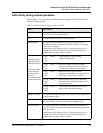
LED activity during boot
During boot and resets, the four software-controlled LEDs indicate different media card
activities by flashing in specific patterns. Refer to Table 1-1 for a description of each pattern.
RX HB
RX ST0
RX ST1
RX ERR
PWR ON
3V
SW XMIT
MD RCV
TX HB
TX ST0
TX ST1
TX ERR
SW RCV
MD XMIT
“Top” end of card “Bottom” end of card
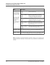
Table 1-1. SP Switch Router Adapter card LED activity during boot and reset
LED Description
• RX HB (green)
• RX ST0 (green)
• RX ST1 (amber)
• RX ERR (amber)
• ON At reset, all LEDs are lit for 1/2 second
• ON as part of on-board diagnostics.
• ON Also tests that LEDs are working.
• ON
• OFF ERROR - During a boot or reset, this pattern indicates
• OFF a checksum error is detected in
• OFF flash memory.
• ON
• ON ERROR - During a boot or reset, this pattern indicates
• OFF that the SRAM fails the memory test.
• ON
• OFF
• ON -> OFF - During loading, HB and RX ST1 flash
• OFF as each section of the code loads.
• OFF
• ON -> OFF