LTRx-512 Installation and User’s Guide
Wiring Diagrams
54
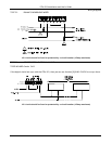
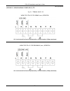
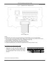
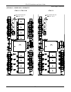
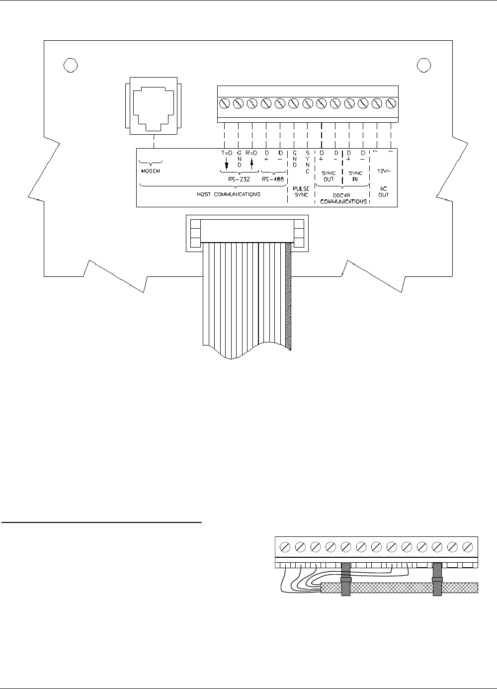
Fig. D7 – COMMUNICATION TERMINAL BLOCK
Rear of Display Unit
NOTES:
1. Twisted-pair (Cat-3/Cat-5) wire connects directly to Terminal Block; up to 2 wires per position
2. Pulse-sync input is same as provided in power supply. One (1) second (min.) dry-contact switch closure
across terminals causes Master to reset time to 12:00AM of nearest date
3. Grounds (GND) are “signal grounds”, not “chassis grounds”
4. Load on non-regulated 12VAC output must be less than 250mA
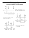
5. For DDC4R communications, the LTRx-512 automatically sets itself as a master or slave
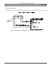
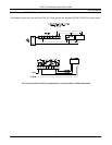
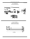
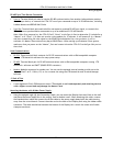
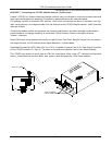
Strain Relief for the Communications Cable
•
Using the two wire tie wraps included in the
installation kit, attach them to the terminal block
as shown in this sample to provide strain relief to
the communications cable. Use any two empty
positions.
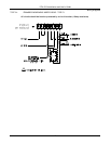
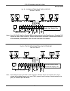
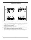
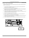
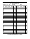
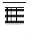
Use the six (6) connections as follows:


