


52 Matrox Graphics Card – User Guide
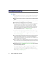
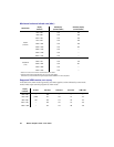
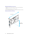
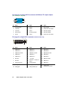
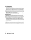
Pin usage for an analog (HD-15) connector with Matrox TV output adapter
(see “TV output”, page 20)
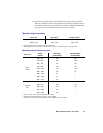
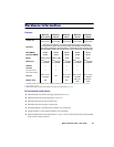
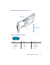
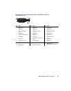
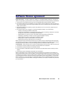
Pin usage for a digital (DVI-I) connector
(Certain models only)
Pin Signal Pin Signal Pin Signal
1 Composite video 6 Ground 11 Not connected
2 Y (S-video) 7 Ground 12 Shorted with 15 by adapter
3 C (S-video) 8 Ground 13 Not used by adapter
4 Not connected 9 Not used by adapter 14 Not used by adapter
5 Ground 10 Ground 15 Shorted with 12 by adapter
Pin Signal Pin Signal Pin Signal
1TMDS data 2– 9TMDS data 1– 17 TMDS data 0–
2 TMDS data 2+ 10 TMDS data 1+ 18 TMDS data 0+
3 TMDS data 2/4 shield 11 TMDS data 1/3 shield 19 TMDS data 0/5 shield
4TMDS data 4– 12 TMDS data 3– 20 TMDS data 5–
5 TMDS data 4+ 13 TMDS data 3+ 21 TMDS data 5+
6 DDC clock 14+5V power 22TMDS clock shield
7 DDC data 15
Ground (for +5 V, Hsync, &
VSync)
23 TMDS clock+
8 Analog vertical sync 16 Hot plug detection 24 TMDS clock–
C1 Analog red C3 Analog blue
C5
Analog ground
(Analog R, G, & B return)
C2 Analog green C4 Analog horizontal sync
1
6
11
5
10
15
24
17
9
1
8
C3
C1 C2
C4
C5