


Installation
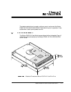
Maxtor D540X-4K 20.4/40.0/60.0/80.0 GB AT 3-5
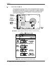
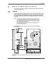
The configuration of the following four jumpers controls the drive’s modes of
operation:
• CS – Cable Select
• DS – Drive Select
• PK– Jumper Parking Position (Slave mode)
• AC– Alternate Capacity
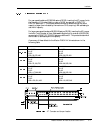
The AT PCB has two jumper locations provided to configure the drive in a system.
The default configuration for the drive as shipped from the factory is with a jumper
across the CS location, and open positions in the DS, PK and AC positions.
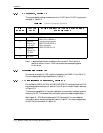
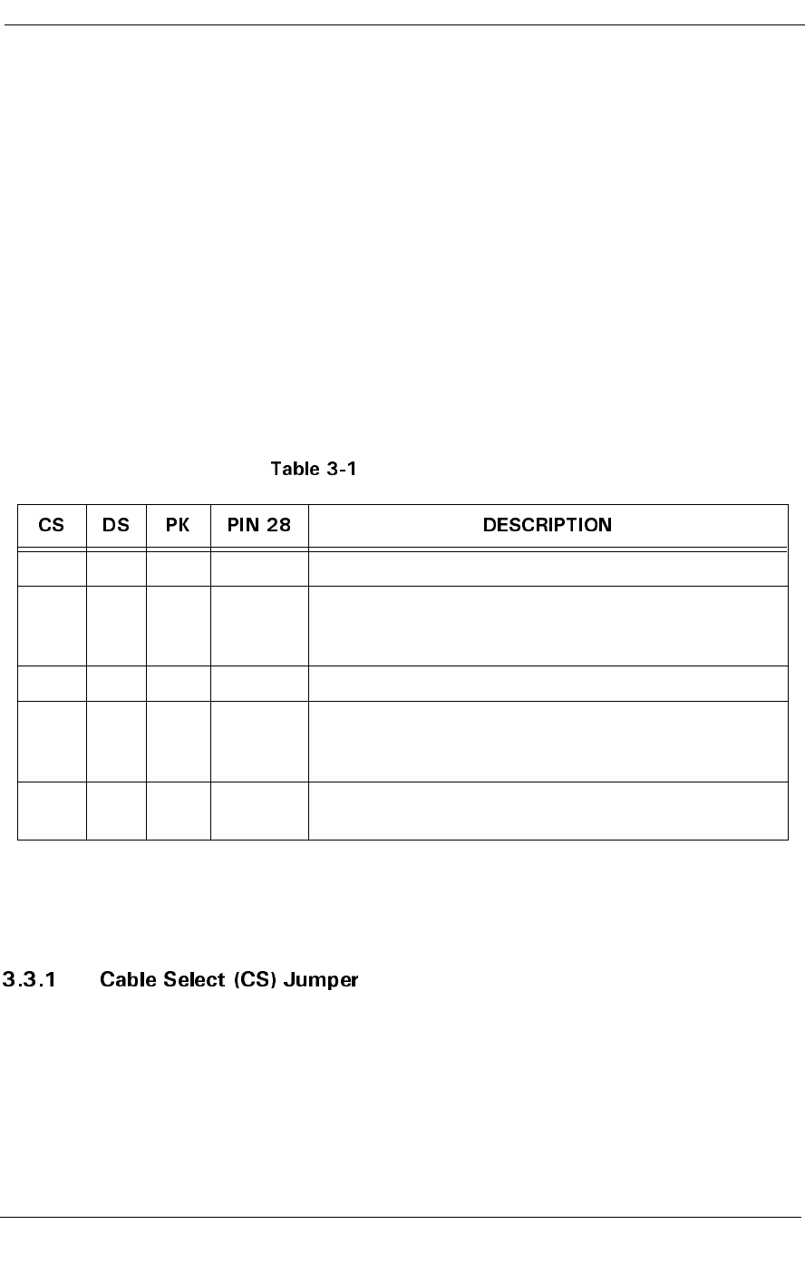
Table 3-1 defines the operation of the master-slave jumpers and their function
relative to pin 28 on the interface. 1 indicates that the specified jumper is installed;
0 indicates that the jumper is not installed.
AT Jumper Options
Note: In Table 3-1, a 0 indicates that the jumper is removed, a 1 indi-
cates that the jumper is installed, and an X indicates that the
jumper setting does not matter.
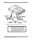
When a Maxtor D540X-4K 20.4/40.0/60.0/80.0 GB AT hard disk drive and
another ATA hard disk drive are daisy-chained together, they can be configured as
Master or Slave either by the CS or DS jumpers. To configure the drive as a Master
or Slave with the CS feature, the CS jumper is installed (1). The drive's position on
the 80 conductor Ultra ATA data cable then determines whether the drive is a
Master (Device 0) or a Slave (Device 1). If the drive is connected to the end of the
Ultra (cable Select) data cable the drive is a Master. If the drive is connected to the
middle connection it is set as a Slave.
0 0 X X Drive is configured as a slave
1 0 X Gnd Drive is configured as Master (Device 0) when
attached to the end of a 80 conductor Ultra ATA
cable
0 1 X X Drive is configured as a Master
1 0 X Open Drive is configured as a Slave (Device 1) when
attached to the middle of a 80 conductor Ultra ATA
cable
1 1 X X Drive is configured as a Master with an attached slave
that does not support DASP