


ATA Bus Interface and ATA Commands
Maxtor D540X-4K 20.4/40.0/60.0/80.0 GB AT 6-17
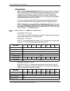
PREREQUISITES - DRDY set equal to one. SMART enabled.
DESCRIPTION - This command returns the device’s attribute thresholds to the host.
Upon receipt of this command from the host, the device sets BSY, reads the attribute
thresholds from non-volatile memory, sets DRQ, clears BSY, asserts INTRQ, and
then waits for the host to transfer the 512 bytes of attribute threshold information from
the device via the Data register.
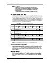
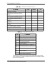
The following defines the 512 bytes that make up the attribute threshold information.
The sequence of active attribute thresholds must appear in the same order as their
corresponding attribute values (see Section 6.5.12.2).
The data structure revision number shall be the same value used in the device attribute
values data structure.
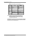
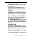
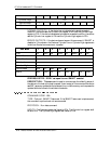
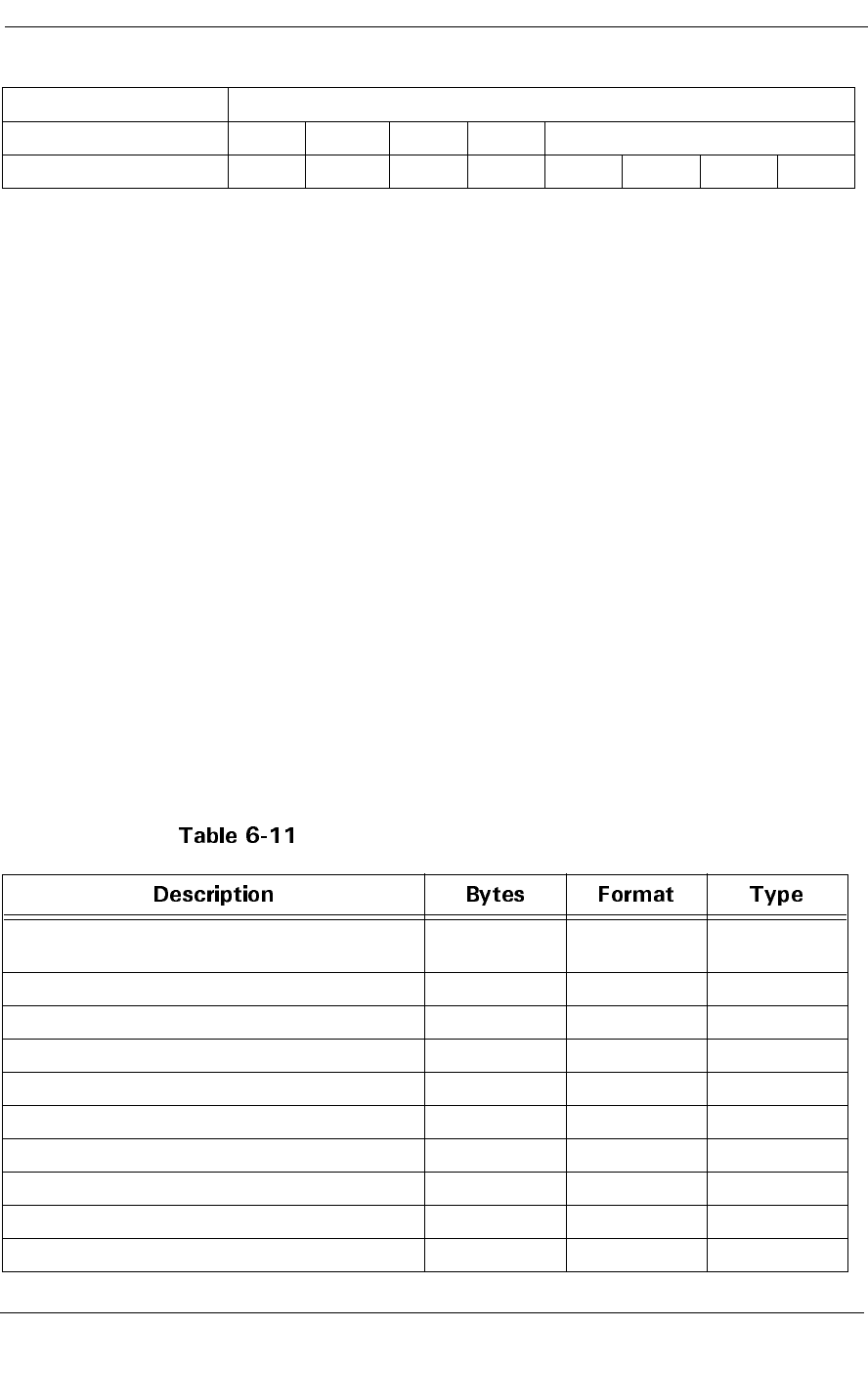
Table 6-11 defines the twelve bytes that make up the information for each threshold
entry in the device attribute thresholds data structure. Attribute entries in the
individual threshold data structure must be in the same order and correspond to the
entries in the individual attribute data structure.
The attribute ID numbers are vendor specific. Any non-zero value in the attribute ID
number indicates an active attribute.
Attribute threshold values are to be set at the factory and are not changeable in the
field.
The data structure checksum is the two’s compliment of the result of a simple eight-
bit addition of the first 511 bytes in the data structure.
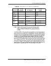
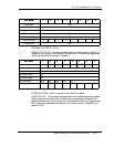
Device Attribute Thresholds Data Structure
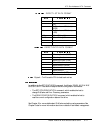
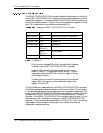
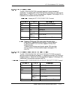
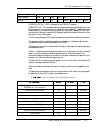
Cylinder High na
Device/Head obs na obs DEV na
Status BSY DRDY DF na DRQ na na ERR
Data structure revision number =
0x0004h for this revision
2 binary Rd only
1st attribute threshold 12 Rd only
.....
.....
.....
30th attribute threshold 12 Rd only
reserved (0x00) 18 Rd only
Vendor specific 131 Rd only
Data structure checksum 1 Rd only
Total bytes 512