


Installation
3-12 Maxtor D540X-4K 20.4/40.0/60.0/80.0 GB AT
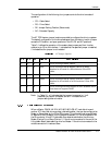
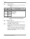
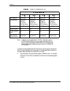
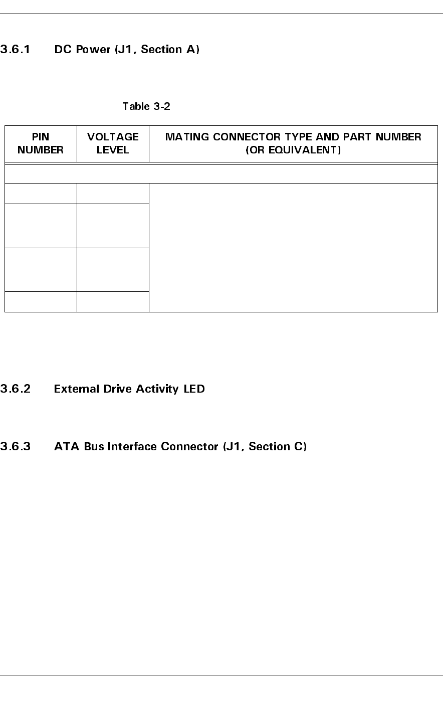
The recommended mating connectors for the +5 VDC and +12 VDC input power
are listed in Table 3-2.
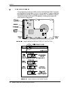
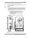
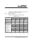
J1 Power Connector, Section A
Note: Labels indicate the pin numbers on the connector. Pins 2 and 3 of
section A are the +5 and +12 volt returns and are connected together
on the drive.
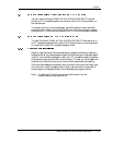
An external drive activity LED may be connected to the DASP-I/O pin 39 on J1.
For more details, see the pin description in Table 6-1.
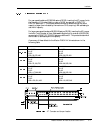
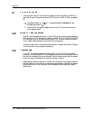
On the Maxtor D540X-4K 20.4/40.0/60.0/80.0 GB AT hard disk drives, the ATA
bus interface cable connector (J1, section C) is a 40-pin Universal Header, as shown
in Figure 3-9.
To prevent the possibility of incorrect installation, the connector has been keyed by
removing Pin 20. This ensures that a connector cannot be installed upside down.
See Chapter 6, “ATA Bus Interface and ATA Commands,” for more detailed
information about the required signals. Refer to Table 6-1 for the pin assignments
of the ATA bus connector (J1, section C).
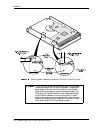
J1 Section A (4-Pin):
1 +12 VDC 4-Pin Connector:
AMP P/N 1-480424-0
Loose piece contacts:
AMP P/N VS 60619-4
Strip contacts:
AMP P/N VS 61117-4
2 Ground
Return for
+12 VDC
3 Ground
Return for
+5 VDC
4+5 VDC