


ATA Bus Interface and ATA Commands
6-14 Maxtor D540X-4K 20.4/40.0/60.0/80.0 GB AT
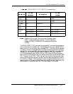
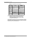
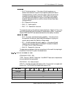
In Table 6-9:
Registers 1F2h
through 1F5h must contain the exact values
shown above. These values function as a key. The drive responds
by setting the ABRT bit in the Error register if the key is not
entered correctly.
To select the drive being reconfigured, set register 1F6h. For
execution of the command to begin, load register 1F7h with F0h
.
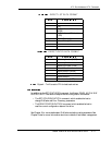
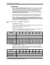
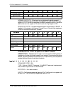
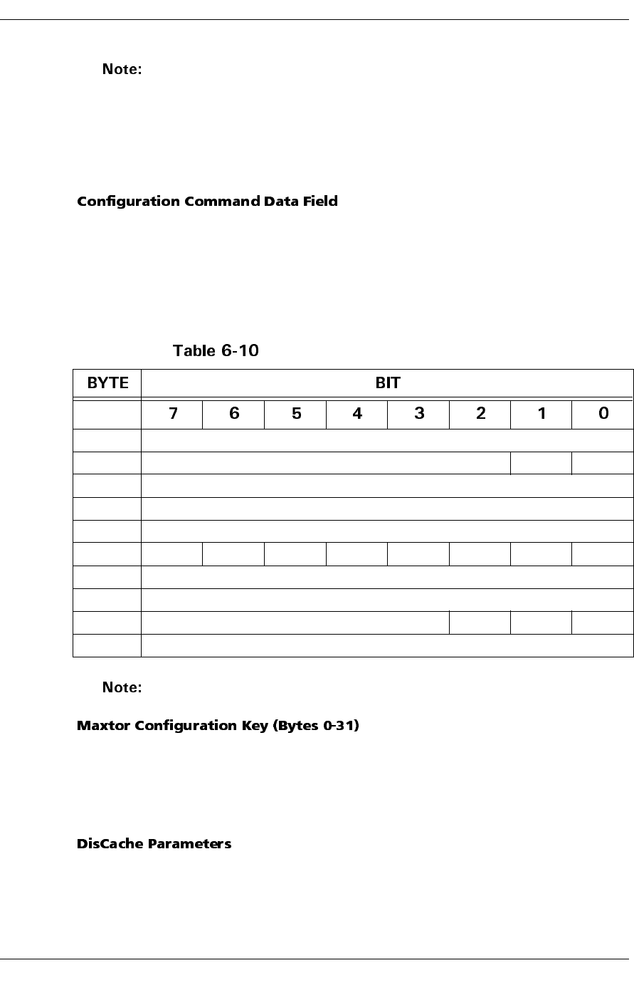
A 512-byte data field is associated with this command. This data field is sent to the
drive through a normal 512-byte write handshake. Table 6-10 shows the format of the
data field. Bytes 0 through 31 of the data field contain additional KEY information.
The drive responds by setting the ABRT bit in the Error register if this information is
not entered correctly. Bytes 32 through 35 control the operation of DisCache. Bytes
36 through 38 control operation of the error recovery procedure. The drive does not
use bytes 40 through 511, which should be set to 0.
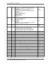
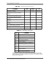
Configuration Command Format
All fields marked RESERVED or N/A should be set to zero.
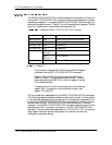
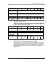
Bytes 0–6 must contain the ASCII characters Q, U, A, N, T, U, and M; byte 7, the
ASCII character space; and bytes 8–20 must contain the ASCII characters C, O, N, F,
I, G, U, R, A, T, I, O, and N. Bytes 21–31 must contain an ASCII space. If this
information is not entered correctly, the drive responds by setting the ABRT bit in
the Error register.
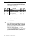
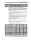
PE – Prefetch Enable (Byte 32, Bit 1): When set to 1, this bit indicates that the
drive will perform prefetching. A PE bit set to 0 indicates that no prefetching will
occur. The CE bit (bit 0) must be set to 1 to enable use of the PE bit. The default
value is 1.
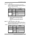
0–31 MAXTOR CONFIGURATION KEY
32 RESERVED = 0 PE CE
33 RESERVED
34 RESERVED = 0
35 RESERVED = 0
36 AWRE ARR N/A RC EEC N/A N/A DCR
37 NUMBER OF RETRIES
38 ECC CORRECTION SPAN
39 RESERVED = 0 WCE RUEE 0
40–511 RESERVED = 0