


Basic Principles of Operation
5-6 Maxtor D540X-4K 20.4/40.0/60.0/80.0 GB AT
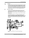
The integrated µProcessor, Disk Controller, and ATA Interface Electronics have nine
functional modules (described below):
• µProcessor
• Digital Synchronous Spoke (DSS)
• Error Correction Code (ECC) Control
• Formatter
• Buffer Controller
• Servo Controller, including PWM
• Serial Interface
• ATA Interface Controller
• Motor Controller
The µProcessor core provides local processor services to the drive electronics under
program control. The µProcessor manages the resources of the Disk Controller, and
ATA Interface internally. It also manages the Read/Write ASIC (Application Specific
Integrated Circuit), and the Spindle/VCM driver externally.
The DSS decodes servo information written on the drive at the factory to determine
the position of the read/write head. It interfaces with the read/write channel, process
timing and position information, and stores it in registers that are read by the servo
firmware.
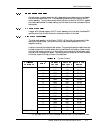
The Error Correction Code (ECC) Control block utilizes a Reed-Solomon encoder/
decoder circuit that is used for disk read/write operations. It uses a total of 36
redundancy bytes organized as 32 ECC (Error Correction Code) bytes with four
interleaves, and four cross-check bytes. The ECC uses eight bits per symbol and four
interleaves. This allows quadruple-burst error correction of at least 96, and as many as
128 bits in error.
The Formatter controls the operation of the read and write channel portions of the
ASIC. To initiate a disk operation, the µProcessor loads a command into the ASIC
registers.
The Formatter also directly drives the read and write gates (
RG, WG) and Command
Mode Interface of the Read/Write ASIC and the R/W Preamplifier, as well as passing
write data to the Precompensator circuit in the Read/Write ASIC.