McDATA 4416 Fibre Channel Switch Module Installation Guide
1-4
Fibre Channel Ports
Fibre Channel Ports
The switch module has 6 external Fibre Channel ports through which to
connect to devices or other switches and 10 internal ports connecting to the
server midplane. Each of the external Fibre Channel ports is served by a Small
Form-Factor Pluggable (SFP) optical transceiver and is capable of 1-Gbps,
2-Gbps, or 4-Gbps transmission. SFPs are hot-pluggable. External ports can
self-discover both the port type and transmission speed when connected to
public devices or other switches. The internal ports operate at 1-Gbps or
2-Gbps.
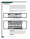
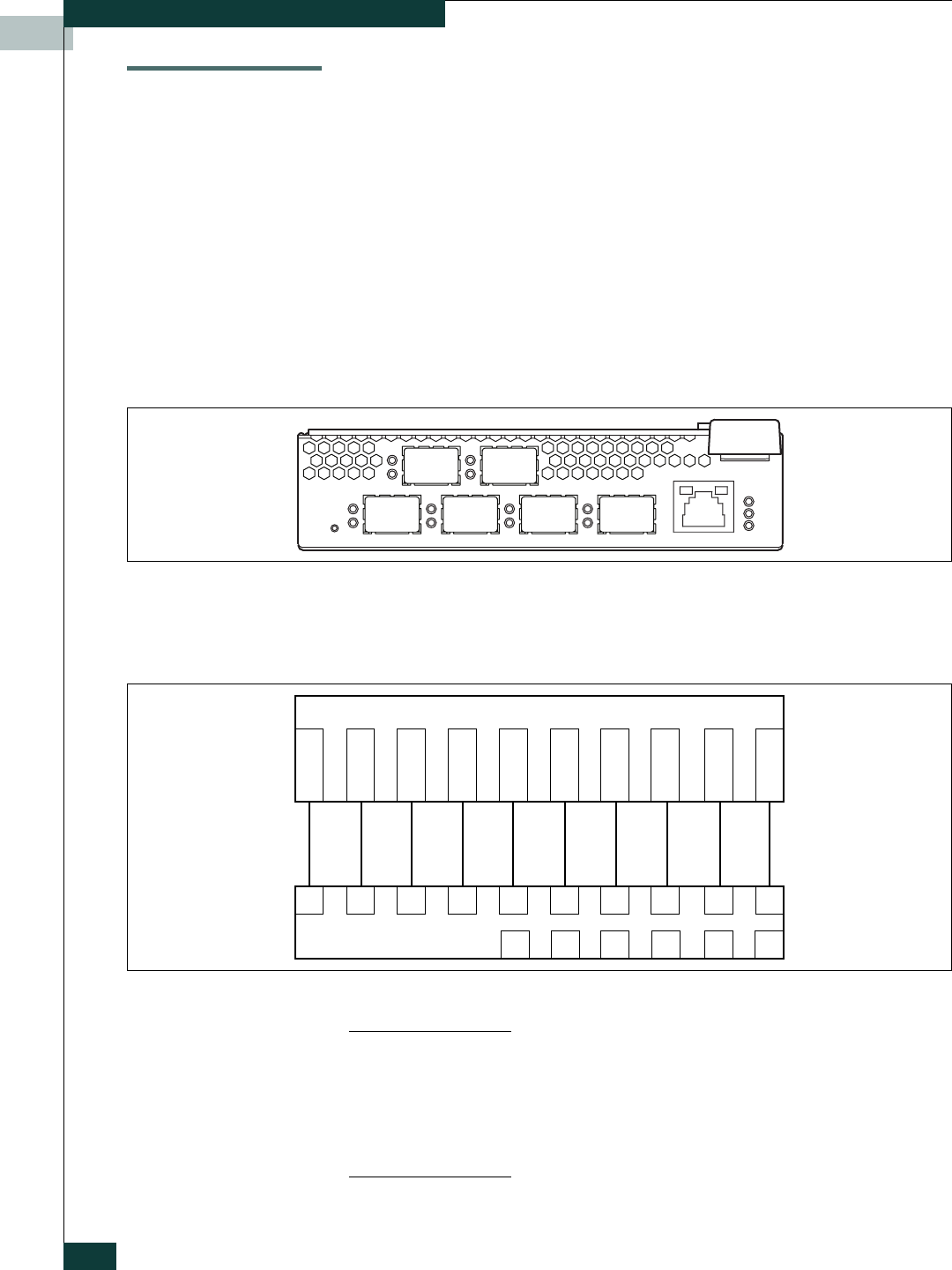
The external ports are named Ext10, Ext11, Ext12, Ext13, Ext14, and Ext15 and
are numbered 10–15 as shown in Figure 1-4. The external port LEDs are
located to the left their respective ports and provide port login and activity
status information.
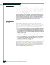
Figure 1-4. Fibre Channel Ports
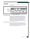
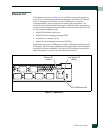
Internal ports are named Int0–Int9 and numbered 0–9. The port numbers 0–9
correspond to server blades 1–10 as shown in Figure 1-5.
Figure 1-5. Internal Port/Server Blade Mapping
NOTE: The switch module comes from the factory as a 12-port switch, enabling
external ports 10–13 and internal ports 0–7 . You can upgrade the switch module to
enable the remaining external ports (14, 15) and internal ports (8, 9) through the
purchase of the Port Activation PFE key. Refer to the McDATA Switch Module
Management Guide for information about installing a PFE key. For additional McDATA
PFE keys, please contact your McDATA representative or visit the web site at
www.mcdata.com.
10 11
12 13
14 15
10 11
01234567 89
12 13 14
15
Switch Module Ports
123456
78910
Server Blades


