


McDATA 4416 Fibre Channel Switch Module Installation Guide
3-4
Installing a Switch
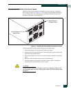
When energized, the switch module responds in the following sequence:
1. The switch module LEDs (Identifier, Input Power, System Fault)
illuminate followed by all port Logged-In LEDs.
2. After a couple seconds the System Fault LED is extinguished while the
Input Power LED remains illuminated.
3. After approximately one minute, the POST executes.
4. After about another minute, the POST is complete, all LEDs are
extinguished except the Input Power LED. The Input Power LED remains
illuminated indicating that the switch logic circuitry is receiving DC
voltage. If not, contact your authorized maintenance provider.
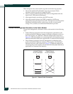
Connect the Management Workstation to the Switch Module
Connect the management workstation to the switch module in the following
ways:
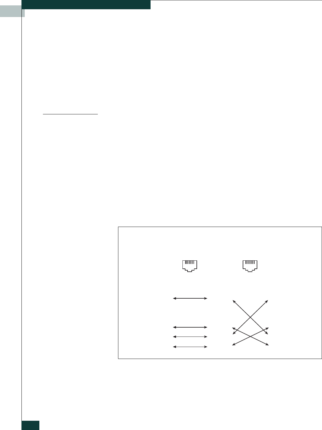
• Indirect Ethernet connection from the management workstation to the
switch module RJ-45 Ethernet connector through an Ethernet switch or a
hub. This requires a 10/100 Base-T Ethernet straight cable as shown in
Figure 3-2. With this method, you can manage the switch module with the
McDATA Embedded Web Server application or Command Line Interface.
• Direct Ethernet connection from the management workstation to the
switch module RJ-45 Ethernet connector. This requires a 10/100 Base-T
Ethernet cross-over cable as shown in Figure 3-2. With this method, you
can manage the switch module with the McDATA Embedded Web Server
application or Command Line Interface.
Figure 3-2. Ethernet Cable Connections
81
8
1
2
7
6
5
4
3
8
1
2
7
6
5
4
3
81
8
1
2
7
6
5
4
3
8
1
2
7
6
5
4
3
Direct Ethernet
RJ-45 Connection
Indirect Ethernet
RJ-45 Connection