


PCI-DAS64/M2/16 User's Guide Installing the PCI-DAS64/M2/16
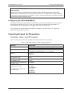
Pin out – auxiliary DIO connector
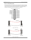
The auxiliary digital connector can be accessed using a variety of cabling schemes. To bring the 40-pin header
out to a bracket at the back of the PC, use a BP40-37 adapter. This terminates in a CIO-DIO series compatible
connector to which you can connect a CIO-MINI37 or CIO-TERMINAL screw terminal board using a C37FF-x
or C37FFS-x cable. Other options include direct cabling using a C40-37F-x (which maintains CIO-DIO
compatibility), or using the C40FF-x cable with the CIO-MINI40 screw terminal board.
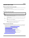
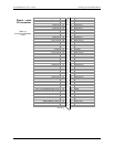
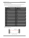
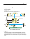
Table 2-4. Auxiliary digital connector pin out
NC 1
• •
2 PC +5V
NC 3
• •
4 DIG GND
FIRSTPORTB Bit 7 5
• •
6 FIRSTPORTC Bit 7
FIRSTPORTB Bit 6 7
• •
8 FIRSTPORTC Bit 6
FIRSTPORTB Bit 5 9
• •
10 FIRSTPORTC Bit 5
FIRSTPORTB Bit 4 11
• •
12 FIRSTPORTC Bit 4
FIRSTPORTB Bit 3 13
• •
14 FIRSTPORTC Bit 3
FIRSTPORTB Bit 2 15
• •
16 FIRSTPORTC Bit 2
FIRSTPORTB Bit 1 17
• •
18 FIRSTPORTC Bit 1
FIRSTPORTB Bit 0 19
• •
20 FIRSTPORTC Bit 0
DIG GND 21
• •
22 FIRSTPORTA Bit 7
NC 23
• •
24 FIRSTPORTA Bit 6
DIG GND 25
• •
26 FIRSTPORTA Bit 5
NC 27
• •
28 FIRSTPORTA Bit 4
DIG GND 29
• •
30 FIRSTPORTA Bit 3
NC 31
• •
32 FIRSTPORTA Bit 2
DIG GND 33
• •
34 FIRSTPORTA Bit 1
PC +5V 35
• •
36 FIRSTPORTA Bit 0
DIG GND 37
• •
38 NC
NC 39
• •
40 NC
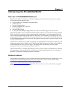
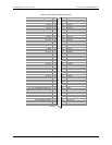
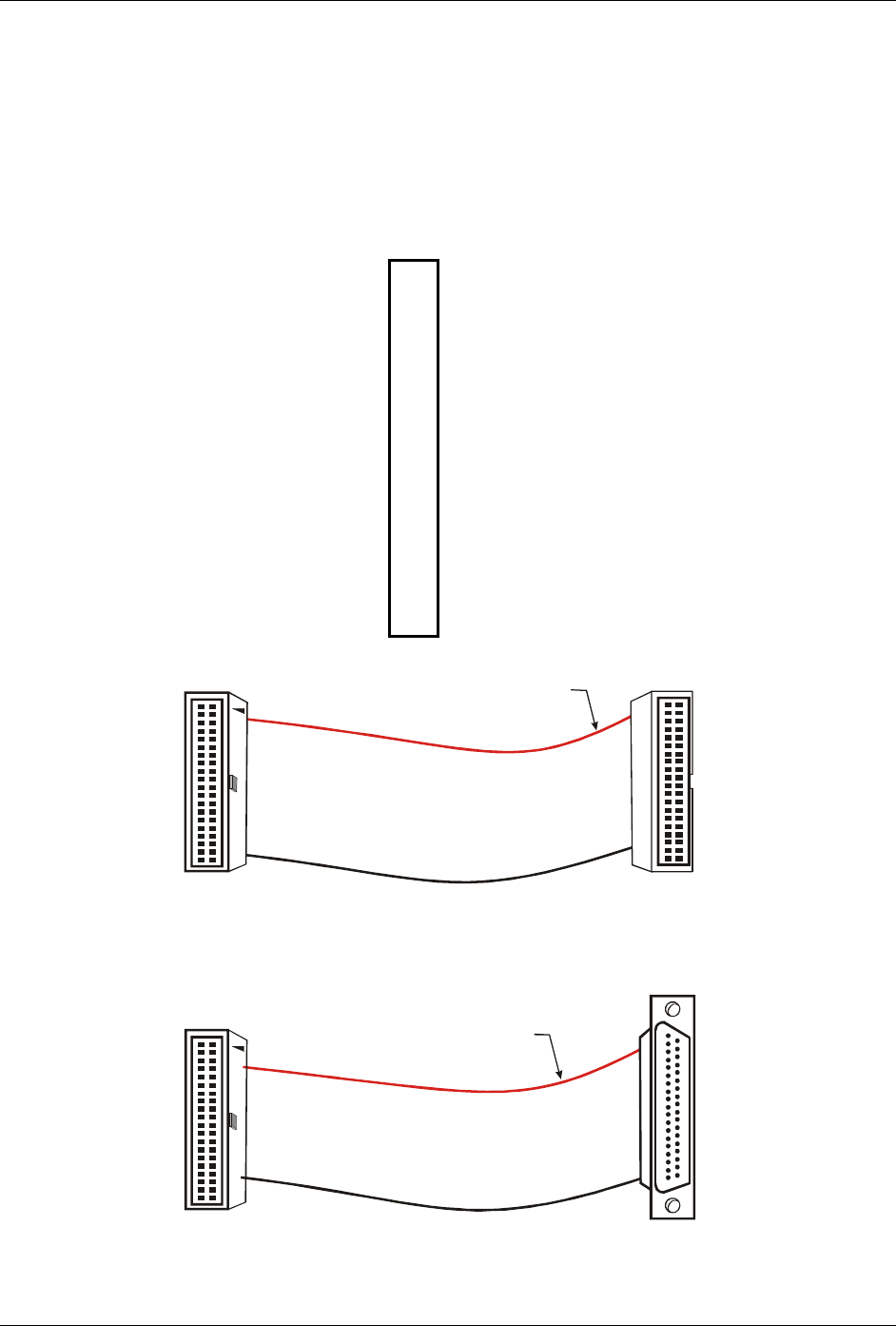
The red stripe
identifies pin # 1
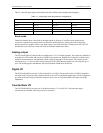
40-pin Female
IDC Connector
1
2
39
40
40-pin Female
IDC Connector
1
2
39
40
Figure 2-3. C40FF-x cable
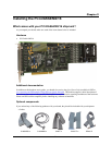
20
1
37
19
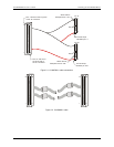
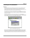
The red stripe
identifies pin # 1
37-pin Female
Dsub Connector
40-pin Female
IDC Connector
1
2
39
40
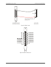
Figure 2-4. C40-37F-x cable
2-7