Chapter 4
Functional Description
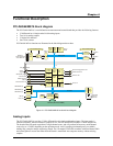
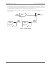
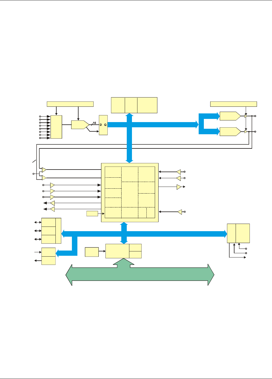
PCI-DAS64/M2/16 block diagram
The PCI-DAS64/M2/16 is a multifunction measurement and control board that provides the following features:
! 32 differential or 64 single-ended 16-bit analog inputs
! Two 16-bit analog outputs
! 32 digital I/O channels
! One 16-bit counter
PCI-DAS64/M2/16 functions are illustrated in the block diagram shown here.
Gain and Offset Autocal
2 MHz
EOC
Memory Bus
32K x 16
SRAM
Gain and Offset Autocal
DAC0
16-bit, 100 k zH
DAC1
16-bit, 100 k zH
D/A OUT0
D/A OUT1
External D/A Trigger/Pacer Gate
D/A External Pacer In
DAC Pacer Out
Interrupt In
16
Control
User
CNTR
0
Local Bus
ADC
CNTL
Trigger
CNTL
ADC
Pacer
Sample
CNTL
Control /
Status
Regs
STC
Memory
CNTL
Queue
CNTL
Decoder
DAC
CNTL
DAC
Pacer
DAC RT
CNTL
DMA
CTRL
IRQ
CTRL
40 MHz
TRIG_LO TRIG_HI
Analog
Trigger
A/D Start/Stop Trigger
A/D Pacer Gate
A/D External Pacer
SSH Out
A/D Internal Pacer Out
24-bits DIO
FIRSTPORTA (7:0)
FIRSTPORTB (7:0)
FIRSTPORTC (7:0)
DIN (3:0)
DOUT (3:0)
PortA
PortB
PortC
Control
Inputs
Outputs
Boot
EEPROM
PCI Bridge
w/BUS Master
16
DMA
C0H
DMA
CH1
PCI Bus (5V, 32-bit, 33 M z)H
Holding
REG
Queue
Buffer
(8K)
DAC 0/1
Buffer
(16K)
ADC
Buffer
(8K)
CTR1 GATE
CTR1 CLK
CTR1 OUT
Analog In
64-CH single-ended
32-CH differential
16-bit
ADC
Mux
&
Gain
Figure 4-1. PCI-DAS64/M2/16 functional bock diagram
Analog inputs
The PCI-DAS64/M2/16 provides 32 fully differential or 64 single-ended analog inputs. The input mode is
software selectable, with no switches or jumpers to set. The PCI-DAS64/M2/16 offers a 2 MHz sample rate.
The board offers full speed acquisition in single channel scans, and will perform full accuracy multi-channel
scans of up to 1.5 MHz, depending on the operating mode. An 8 K sample gain/channel queue is available
making long, complex sample sequencing simple. An 8 K sample FIFO buffer combines with Bus-Master DMA
and scatter-gather to assure data taken from the board is transferred into computer memory without missing
samples.
4-1


