


Chapter 6
Specifications
Typical for 25 °C unless otherwise specified.
Specifications in italic text are guaranteed by design.
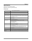
Analog input
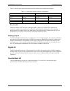
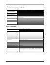
Table 1. Analog input specifications
A/D converter type Sub-ranging sampling ADC
Resolution 16 bits
Number of channels 32 differential or 64 single-ended, software selectable
Input ranges
(software programmable)
±5 V, ±2.5 V, ±1.25 V, ±0.625 V, 0 to 5 V, 0 to 2.5 V, 0 to 1.25 V
Polarity Unipolar/bipolar, software selectable
A/D pacing
(software programmable)
! Internal counter – ASIC
! External source (A/D external pacer). The total number of sample clocks must be at least
5 greater than the total number of samples desired. This is required to accommodate the
pipelined architecture of the ADC.
! Software polled
Burst mode Software selectable option. Valid for a fixed input range only.
Burst rate = 667 nS.
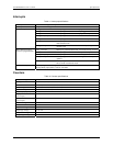
A/D gate sources
! External digital (A/D pacer gate)
! External analog (analog trigger in)
External digital: Programmable, active high or active low, level or edge A/D gating modes
External analog: Software-configurable for:
! Above or below reference
! Positive or negative hysteresis
! In or out of window.
Trigger levels set by DAC0 and/or DAC1.
A/D trigger sources
! External digital (A/D start trigger in and A/D stop trigger in)
! External analog (Analog Trigger In)
A/D triggering modes
! External digital: Software-configurable for rising or falling edge.
! External analog: Software-configurable for positive or negative slope. Trigger levels set
by DAC0 and/or DAC1.
! Pre-/post-trigger: Unlimited number of pre-trigger samples, 16 Meg post-trigger
samples. Compatible with both digital and analog trigger options.
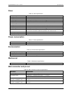
Data transfer
! From 8 k RAM buffer via DMA (demand or non-demand mode) using scatter gather.
! Programmed I/O
Configuration memory 8 K words
Channel/gain queue Up to 8 K elements. Programmable channel, gain, and offset.
A/D conversion time 500 nS
Calibration Auto-calibration, calibration factors for each range stored on board in non-volatile RAM.
6-4