


PCI-DAS64/M2/16 User's Guide Installing the PCI-DAS64/M2/16
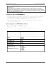
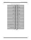
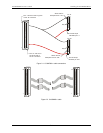
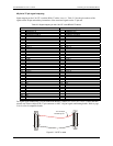
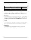
40-pin to 37-pin signal mapping
Signal mapping on the C40-37F-x and the BP40-37 cables is not 1:1. lists the pin numbers of the
signals on the 40-pin end and the pin numbers of the associated signals on the 37-pin end.
Table 2-5
Table 2-5. Signal mapping on the C40-37F-x and BP40-37F cables
40-pin cable end 37-pin cable end
Pin Signal Name Pin Signal Name
1 INTERRUPT IN 1 INTERRUPT IN
2 +5V 20 +5V
3 INTERRUPT ENABLE 2 INTERRUPT ENABLE
4 GND 21 GND
5 Port B 7 3 Port B 7
6 Port C 7 22 Port C 7
7 Port B 6 4 Port B 6
8 Port C 6 23 Port C 6
9 Port B 5 5 Port B 5
10 Port C 5 24 Port C 5
11 Port B 4 6 Port B 4
12 Port C 4 25 Port C 4
13 Port B 3 7 Port B 3
14 Port C 3 26 Port C 3
15 Port B 2 8 Port B 2
16 Port C 2 27 Port C 2
17 Port B 1 9 Port B 1
18 Port C 1 28 Port C 1
19 Port B 0 10 Port B 0
20 Port C 0 29 Port C 0
21 GND 11 GND
22 Port A 7 30 Port A 7
23 N/C 12 N/C
24 Port A 6 31 Port A 6
25 GND 13 GND
26 Port A 5 32 Port A 5
27 N/C 14 N/C
28 Port A 4 33 Port A 4
29 GND 15 GND
30 Port A 3 34 Port A 3
31 N/C 16 N/C
32 Port A 2 35 Port A 2
33 GND 17 GND
34 Port A 1 36 Port A 1
35 +5V 18 +5V
36 Port A 0 37 Port A 0
37 GND 19 GND
38 N/C
39 N/C
40 N/C
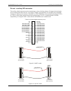
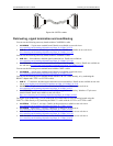
For digital signal conditioning, you can connect the BP40-37 cable to a C37FF-x or C37FFS- x cable, and then
connect one of these cables to the 37-pin connector on MCC’s digital signal conditioning boards. Refer to page
2-10 for a list of compatible boards.
20
1
37
19
20
1
37
19
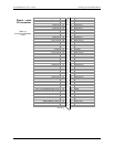
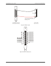
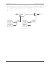
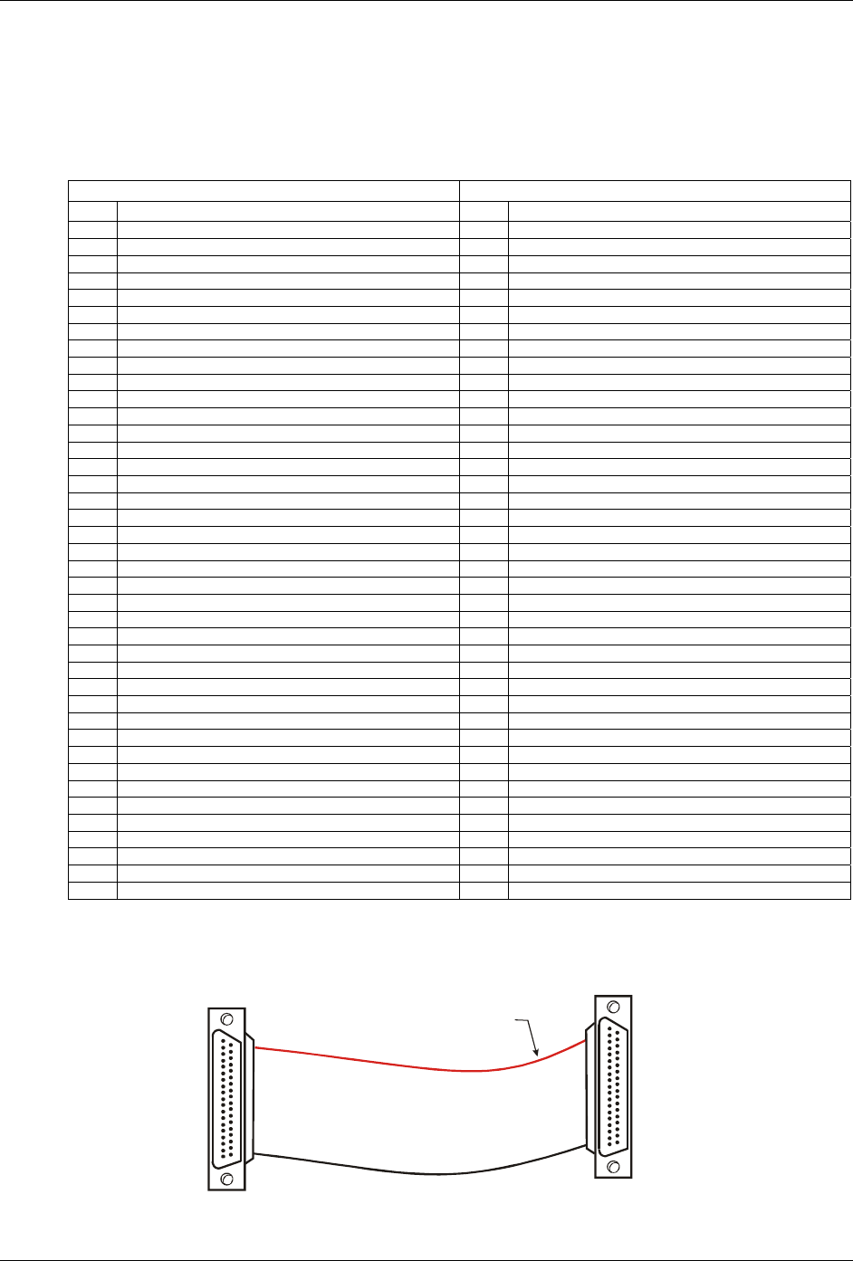
The red stripe
identifies pin # 1
Figure 2-7. C37FF-x cable
2-9