


Figures
figure description . . . . . . . . . . . . . . . . . . . . . . . . . . . . . . . . . . . . . . . . . . . . . . . . .page
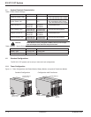
1-1: Tower Configurations with Power Module, Battery Module,
and optional Transformer Module. . . . . . . . . . . . . . . . . . . . . . . . . . . . . . .1 — 4
1-2: Rack Configurations with Power Module, Battery Module, and
Transformer Module . . . . . . . . . . . . . . . . . . . . . . . . . . . . . . . . . . . . . . . . .1 — 5
1-3: Rear panel of the Power Module. . . . . . . . . . . . . . . . . . . . . . . . . . . . . . .1 — 6
1-4: Rear Panel of the Battery Module. . . . . . . . . . . . . . . . . . . . . . . . . . . . . .1 — 6
1-5: Rear Panel of the optional Transformer Module. (PN 86003) . . . . . . . . .1 — 7
1-6: View of typical control panel interface. . . . . . . . . . . . . . . . . . . . . . . . . . .1 — 7
1-7: Power Module Rack Mounting Kit. . . . . . . . . . . . . . . . . . . . . . . . . . . . . .1 — 8
1-8: Telescopic rails for the Battery/Transformer/CLA module
Rack mounting. . . . . . . . . . . . . . . . . . . . . . . . . . . . . . . . . . . . . . . . . . . . .1 — 8
1-9: Typical back-up time with multiple EXB’s at full load. . . . . . . . . . . . . . . . .1 — 9
1-10: Typical Battery Integration kit with casters setup. . . . . . . . . . . . . . . . . .1 — 10
1-11: Typical Transformer Module contents and connections. . . . . . . . . . . . .1 — 11
1-12: Connection for CLA Module and EX 5/7/11 RT. . . . . . . . . . . . . . . . . . .1 — 12
2-1: Contents of Standard HV EX 5RT (PN 86050)
/ EX 7RT (PN 86070) / EX 11RT (PN 86110) System. . . . . . . . . . . . . .2 — 3
2-2: Tower Configuration of Standard System and Optional
Transformer Module. . . . . . . . . . . . . . . . . . . . . . . . . . . . . . . . . . . . . . . . .2 — 4
2-3: Typical orientation of the logo and control panel.
(Power Module shown) . . . . . . . . . . . . . . . . . . . . . . . . . . . . . . . . . . . . . .2 — 5
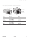
2-4: Accessing Battery Pack. . . . . . . . . . . . . . . . . . . . . . . . . . . . . . . . . . . . . .2 — 6
2-6: Rack mounting of the power module onto the rails. . . . . . . . . . . . . . . . .2 — 7
2-7a: Rear Support Brackets. . . . . . . . . . . . . . . . . . . . . . . . . . . . . . . . . . . . . . .2 — 8
2-7b: Input/Output Box Bracket System. . . . . . . . . . . . . . . . . . . . . . . . . . . . . .2 — 8
2-8: RS232 Communication Cable Connection. . . . . . . . . . . . . . . . . . . . . . . .2 — 9
2-9: Relay Pin Connections for Communication Port. . . . . . . . . . . . . . . . . .2 — 10
2-10: Communication Card Slot with SNMP/Web Network
Management Card installed. . . . . . . . . . . . . . . . . . . . . . . . . . . . . . . . . .2 — 10
2-10a: Activation of remote power off function using a contact
normally open switch. . . . . . . . . . . . . . . . . . . . . . . . . . . . . . . . . . . . . . . .2 — 12
2-10b: Activation of remote power off function using a contact
normally closed switch. . . . . . . . . . . . . . . . . . . . . . . . . . . . . . . . . . . . . .2 — 12
2-12a: Step 1 & 2; Typical plastic and metal coupling installations. . . . . . . . . .2 — 13
2-12b: Step 3; Typical Straight Metal Conduit installation. . . . . . . . . . . . . . . .2 — 14
2-12c: I/O Box Terminal Block Diagram. . . . . . . . . . . . . . . . . . . . . . . . . . . . . . .2 — 14
2-13: Normal AC Input and Output Cables installation. . . . . . . . . . . . . . . . . .2 — 15
2-14: View of EX RT transformer connected downstream for
120/208/240 Vac outputs (shown with one EXB). . . . . . . . . . . . . . . . . .2 — 16
2-15: Normal AC Input, Bypass AC, and Output Cables Installation. . . . . . .2 — 17
2-16: Accessing Terminal Blocks for Input and Output power cables. . . . . . .2 — 18
2-17: Rear view of battery module cable connections. . . . . . . . . . . . . . . . . .2 — 19
2-18: Rear view of CLA module cable battery and AC input connections. . .2 — 20
EX 5/7/11 RT System
Contentsc iv 86-86000-00 A01