


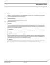
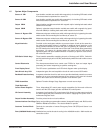
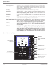
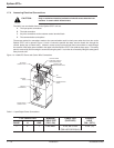
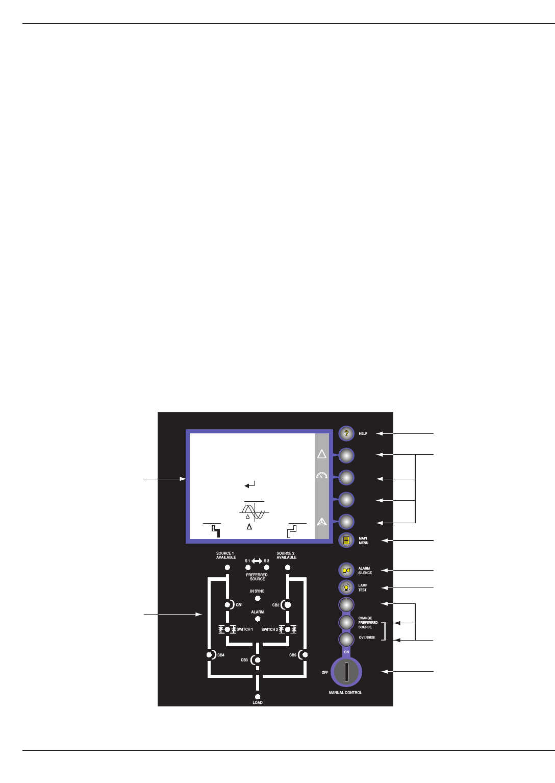
Front Display Panel Comprised of a 4.7” x 3.6” LCD with associated “soft” keys for monitoring status,
alarms, changing certain settings and performing
certain operations; an LED “mimic”
diagram display for indicating switch status and power flow; and manual control
pushbuttons for manual transfer functions.
Hard Keys Manual, dedicated keys (pushbuttons) that have a single function.
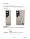
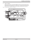
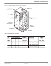
Input Power The Epsilon STS™ is normally connected to two separate, independent sources,
Source S1 and Source S2. Power from each source can be provided by the
electrical utility company, a generator or a UPS.
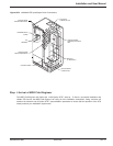
SCR Switch A set of three pairs of SCR's that function as a three-phase, AC switch for each
source.
Soft Keys Programmable keys (pushbuttons) associated with the LCD, that can be used for
several different functions depending on the displayed screen
Static Transfer Switch (STS) All components within the Epsilon STS™ cabinet that function as a system to
transfer the critical load between two independent sources of power using solid-
state SCR switches or bypass to either source using manual bypass switches
PMM
2
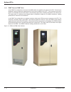
Plus A configuration with the Epsilon STS™ and PMM
2
cabinet. The input of the PMM
2
cabinet is supplied by the output of the STS. Refer to the PMM
2
manual 86-505004-
00 for more details.
PMM
2
Ultra A configuration with the Epsilon STS™ and PMM
2
cabinet. PMM
2
isolation trans-
formers feed each STS input source upstream of the STS. The transformer
secondary output of the PMM
2
-1 (left cabinet) supplies the Source-1 input and
PMM
2
-2 (right cabinet) supplies Source-2 input of the STS cabinet. The output of
the STS connects to the output busbars of the PMM
2
-1 and PMM
2
-2 cabinets,
feeding panelboards or main frame circuit beakers. Refer to the PMM
2
manual 86-
505004-00 for more details.
Figure 1-3: Operator Input Display.
Epilson STS
TM
Introduction1 — 6 86-504004-00 B03
RETURN TO
PREFERRED
SOURCE
LIMITS
Synchro
= 0º
A 2A B 1A C 3A
0 KW 1 KVA
NORMAL OPERATION
PF 0.0
Preferred
UPS 1
60.0 HZ
A-B 503 V
B-C 501 V
C-A 507 V
UPS 2
60.0 HZ
A-B 504 V
B-C 503 V
C-A 508 V
!
volt
HELP KEY
LCD GRAPHIC
DISPLAY
LED STATUS &
MIMIC DIAGRAM
"SOFT" FUNCTION
KEYS
MAIN MENU KEY
ALARM SILENCE KEY
LAMP TEST KEY
MANUAL OPERATIONS
KEY
MANUAL CONTROL
KEYED SWITCH