


Installation and User Manual
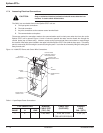
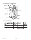
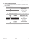
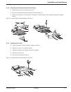
2.2.1 Conduit Plate Location (bottom entry)
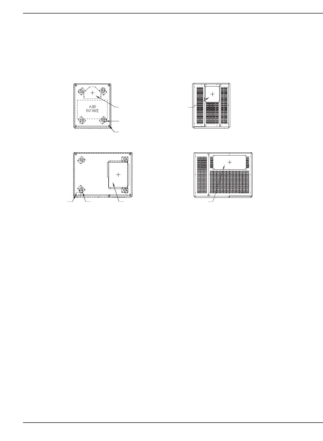
Cable entry through the bottom is the standard preferred design for the Epsilon STS™ cabinet. Please see the
following figure for the location of the bottom entry conduit plate.
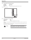
Figure 2-2: 200A /400/600A STS Cabinet Footprint and Top View.
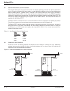
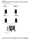
2.3 Source #1 AC Input Connections
The connections to be made are the three phases, neutral (if used) and ground cables of input AC Source #1 to the
STS. The main 3-phase cables of input Source #1 are terminated at the Source #1 input busbars. Neutral (if
supplied) and Ground cables are terminated at the Neutral (N) and Ground (GND) busbars respectively. All cables
from Source #1 should be run in a single conduit separately from all other cables (power supply or computer-system
interconnection cables). They should not pass near interference-emitting
equipment or sensitive loads. Complete
wiring instructions for your installation
are provided on the installation drawings supplied with the equipment. See
Figure 1-5 and 1-6, refer to table 1-1 and 1-2 for details.
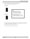
2.3.1. Source #2 AC Input Connections
The connections to be made are the three phases, neutral (if used) and ground cables of input AC Source #2 to the
STS. The main 3-phase cables of input Source #2 are terminated at the Source #2 input busbars. Neutral (if
supplied) and Ground cables are terminated at the Neutral (N) and Ground (GND) busbars respectively. All cables
from Source #2 should be run in a single conduit separately from all other cables (power supply or computer-system
interconnection cables). They should not pass near interference-emitting
equipment or sensitive loads. Complete
wiring instructions for your installation
are provided on the installation drawings supplied with the equipment. See
Figure 1-5 and 1-6, refer to table 1-1 and 1-2 for details.
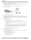
2.3.2 AC Output Connections
The connections to be made are the three phases, neutral(if used) and ground cables from the load to the STS.
The main 3-phase cables from the load are terminated at the Output busbars. Neutral(if supplied) and Ground
cables are terminated at the Neutral(N) and Ground(GND) busbars respectively. All cables from the load should be
run in a single conduit separately from all other cables(power supply or computer-system interconnection cables).
Installation 2 — 386-504004-00 B03
REMOVABLE
CONDUIT PLATE
8.3 X 8.3 OPENING
LEVELING JACKS
(4 PLACES)
CASTERS
(4 PLACES)
REMOVABLE
CONDUIT PAN
10.0 X 7.0 OPENING
TOP VIEWFOOTPRINT
REMOVABLE
CONDUIT PLATE
20.6 X 7.3 OPENING
LEVELING JACKS CASTERS REMOVABLE
CONDUIT PAN
12.4 X 16.5 OPENING
TOP VIEWFOOTPRINT
200A STS
400/600A STS