2.1 Cabinet Placement and Environment
The complete STS system may consist of more than one cabinet depending on whether the STS is a stand-alone
unit or it is used in conjunction with input isolation or output distribution cabinets such as the Power Management
Module
2
(PMM
2
) cabinets. Cabinets must be arranged in the required positions to ensure proper connections.
When facing the Epsilon STS™ from the front, the standard arrangement provides for any PMM
2
Plus auxiliary
cabinets to be located on the right hand side. The PMM
2
Ultra has cabinets located on both
sides of the STS. The
interconnect cables and side barrier(s) are supplied with the PMM
2
cabinet. The interconnect brackets are
supplied with the Epsilon STS™.
The Epsilon STS™ is intended for use in an environment where control of temperature and humidity is provided.
The maximum operating and recommended environmental parameters are listed in Appendix B.
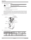
The Epsilon STS™ cabinets generate heat and exhaust air through the top portion of its enclosures. Air intake is
through the lower front or bottom of the cabinet. All other auxiliary cabinets are convection cooled. To assist you
in planning for your HVAC needs, heat rejection data is provided in Table 2.1 for a worst case scenario (i.e.,
maximum rated power output).
Table 2-1: Heat Rejection Data and Rated Current.
Data Rate
STS Module BTU/Hr
200A 5,600
400A 11,400
600A 16,700
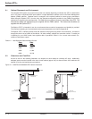
2.2 Clearances and FootPrint
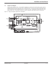
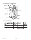
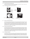
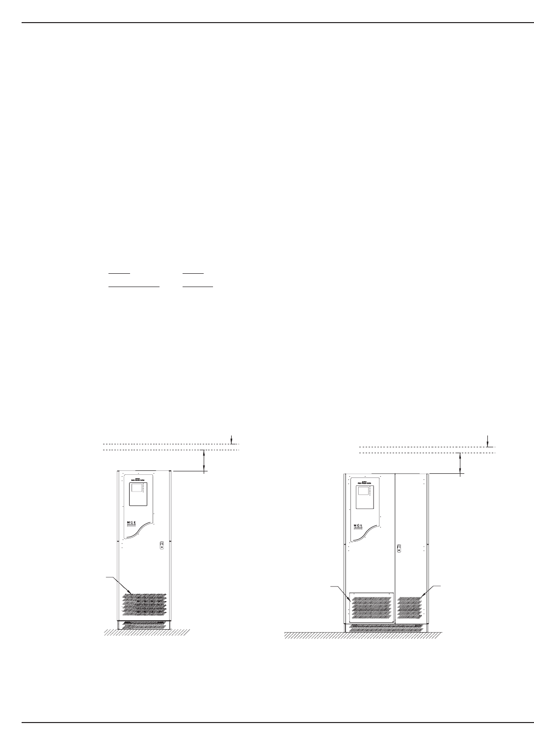
As can be seen in the following illustration, the footprint for each cabinet is nominally 30" deep. Additionally,
adequate space must be included in the front of each cabinet (approx. 36") to allow the door of the cabinet to be
opened for service and maintenance procedures.
Figure 2-1: 200STS and 400/600A STS Cabinet Clearances.
Epilson STS
TM
Installation2 — 2 86-504004-00 B03
12" MIN.
RECOMMENDED FOR
AIR EXHAUST
CEILING
FLOOR
AIR INLET
(DO NOT BLOCK)
12" MIN.
RECOMMENDED FOR
AIR EXHAUST
CEILING
FLOOR
AIR INTAKE
FILTER WINDOW
(DO NOT BLOCK)
AIR INLET
(DO NOT BLOCK)


