


Installation and User Manual
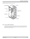
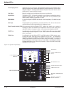
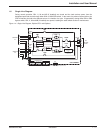
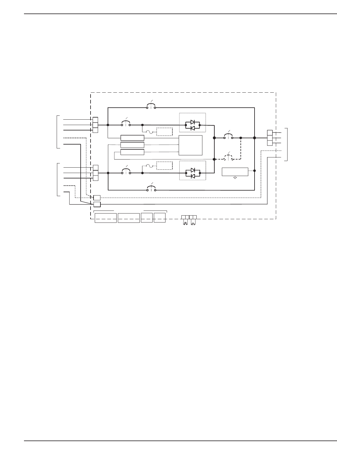
1.6 Single Line Diagram
During normal operation, CB1, 2, 3A and 3B (if installed) are closed and the load receives power from the
designated preferred source through either SW1 or SW2 SCR switch. In the event of a preferred source failure, the
STS will transfer the load to the alternate source in a fraction of a cycle. If bypassed by closing either CB4 or CB5
bypass switch, CB1, 2, 3A and 3B (if installed) are opened, isolating the static switch section for maintenance.
Figure 1-4: Single Line Diagram, Epsilon STS
TM
with Options.
Introduction 1 — 786-504004-00 B03
CB1
A
SOURCE
#1
SW1
B
C
A
B
C
N
G
CB4
CB2
A
SOURCE
#2
SW2
B
C
A
B
C
N
G
CB5
N
G
AC-DC PS 1
AC-DC PS 2
AC-DC PS 3
TVSS 1
(OPTION)
FUSE
CONTROLS
TVSS 2
(OPTION)
FUSE
CB3A
CB3B
(OPTION)
A
TO
CRITICAL
LOAD
B
C
A
B
C
N
G
OUTPUT
SOURCE
S1
INPUT
SOURCE
S2
INPUT
STS CABINET
CB CONTROL
EPO PS
EPO
SHUNT TRIPS
BYPASS LEDs
1
TB1
2 3 4
EPO
(SEE SECTION 2.5.2.1)
SOURCE LOSS TEST
(SEE SECTION 2.5.2.2)
COMMUNICATIONS
RELAY
CARD
(SEE SECT. 2.5.3)
JBUS/MODBUS
CARD
(SEE SECT. 2.5.4)
OPTION
CARD
OPTION
CARD