


Addressing information is divided into three sections in this chapter.
The first section shows memory maps. The maps show the memory
addresses for the functions called through control addresses. The sec-
ond section describes these control addresses, which provide memory
mode selection, RAM write-enable/-protect, and bank switching. The
third section describes additional technical details about status bits,
about the LED indicators on RAMCard, and about RAMCard hard-
ware details.
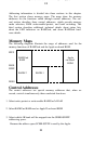
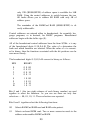
Memory Maps
The following diagrams illustrate the range of addresses used for the
memory functions of RAMCard and the Apple on-board ROM.
FFFF
RAMCard Apple
RAM on-board
ROM
E000
DFFF
BANK 2 BANK 1
D000
Control Addresses
The control addresses are special memory addresses that, when ac-
cessed, control simultaneously three unrelated functions:
1. Select write-protect or write-enable RAMCard’s RAM
2. Select RAMCard RAM read or Apple II on-board ROM
3. Select which 4K bank will be mapped into the $D000-$DFFF
addressing space.
Because the address space $C000-$CFFF is used by the Apple,
22
Because the address space $C000-$CFFF is used by the Apple.
22