


8
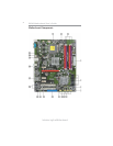
Installing the Motherboard
PXP43 Motherboard User’s Guide
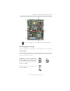
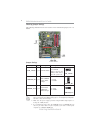
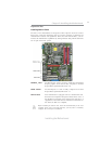
Checking Jumper Settings
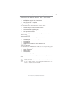
The following illustration shows the location of the motherboard jumpers. Pin 1 is
labeled.
To avoid the system instability after clearing CMOS, we recommend
users to enter the main BIOS setting page to “Load Optimized Defaults”
and then “Save & Exit Setup”.
1.
2.
Make sure the power supply provides enough 5VSB voltage before se-
lecting the 5VSB function.
3.
It is required that users place the USBPWR_F1~2 & USBPWR_R1 cap
onto 2-3 pin rather than 1-2 pin as default if you want to wake up the
computer by USB/PS2 KB/Mouse.
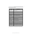
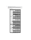
Jumper Settings
Jumper Type Description Setting (default)
CLR_CMOS
3-pin
CLEAR CMOS
1-2: NORMAL
2-3: CLEAR
Before clearing the
CMOS, make sure to
turn the system off.
3-pin
USBPWR_R1
1-2: VCC
2-3: 5VSB
Rear USB/PS2
Power Select
Jumper
3-pin
USBPWR_F1~2
1-2: VCC
2-3: 5VSB
Front Panel
USB Power
Select Jumper
USBPWR_F1~2
CLR_CMOS
USBPWR_R1
1
1
1