


22
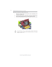
Installing the Motherboard
PXP43 Motherboard User’s Guide
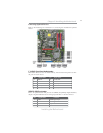
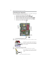
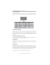
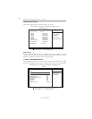
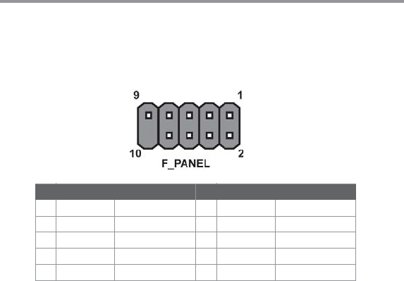
Front Panel Header
The front panel header (F_PANEL) provides a standard set of switch and LED headers
commonly found on ATX or Micr ATX cases. Refer to the table below for informa-
tion:
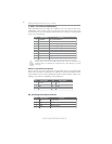
Reset Switch
Supporting the reset function requires connecting pin 5 and 7 to a momentary-
contact switch that is normally open. When the switch is closed, the board resets and
runs POST.
Power/Sleep/Message waiting LED
Connecting pins 2 and 4 to a single or dual-color, front panel mounted LED provides
power on/off, sleep, and message waiting indication.
Hard Drive Activity LED
Connecting pins 1 and 3 to a front panel mounted LED provides visual indication
that data is being read from or written to the hard drive. For the LED to function
properly, an IDE drive should be connected to the onboard IDE interface. The LED
will also show activity for devices connected to the SCSI (hard drive activity LED)
connector.
Power Switch
Supporting the power on/off function requires connecting pins 6 and 8 to a momen-
tary-contact switch that is normally open. The switch should maintain contact for at
least 50 ms to signal the power supply to switch on or off. The time requirement is
due to internal de-bounce circuitry. After receiving a power on/off signal, at least two
seconds elapses before the power supply recognizes another on/off signal.
This concludes Chapter 2. The next chapter covers the BIOS.
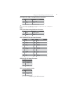
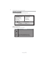
Pin Signal Function Pin Signal Function
1 HD_LED_P Hard disk LED (+)
2 FP PWR/SLP *MSG LED (+)
3 HD_LED_N Hard disk LED (-)
5 RST_SW_N Reset Switch (-)
7 RST_SW_P Reset Switch (+)
9 RSVD Reserved
4 FP PWR/SLP *MSG LED (-)
6 PWR_SW_P Power Switch (+)
8 PWR_SW_N Power Switch (-)
10 Key No pin
* MSG LED (dual color or single color)