


16
Installing the Motherboard
PXP43 Motherboard User’s Guide
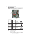
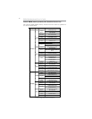
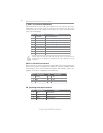
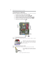
F_USB1~4: Front Panel USB headers
The motherboard has four USB ports installed on the rear edge I/O port array.
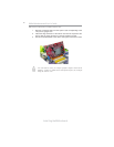
Additionally, some computer cases have USB ports at the front of the case. If you
have this kind of case, use auxiliary USB connector to connect the front-mounted
ports to the motherboard.
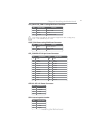
Please make sure that the USB cable has the same pin assignment as
indicated above. A different pin assignment may cause damage or system
hang-up.
1 USBPWR Front Panel USB Power
2 USBPWR Front Panel USB Power
3 USB_FP_P0- USB Port 0 Negative Signal
4 USB_FP_P1- USB Port 1 Negative Signal
5 USB_FP_P0+ USB Port 0 Positive Signal
6 USB_FP_P1+ USB Port 1 Positive Signal
7 GND Ground
8 GND Ground
9 Key No pin
10 NC Not connected
Function
Pin Signal Name
Pin Signal Name Pin Signal Name
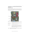
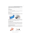
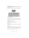
SATA1~6: Serial ATA connectors
These connectors are used to support the new Serial ATA devices for the highest date
transfer rates (3.0 Gb/s), simpler disk drive cabling and easier PC assembly. It elimi-
nates limitations of the current Parallel ATA interface. But maintains register com-
patibility and software compatibility with Parallel ATA.
1 Ground 2 TX+
3 TX- 4 Ground
5 RX- 6 RX+
7 Ground - -
Pin Signal Name
Pin Signal Name
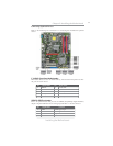
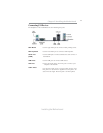
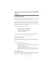
CD_IN: Analog Audio Input connector
Pin Signal Name Function
1 CD_L CD In left channel
2 GND Ground
3 GND Ground
4 CD_R CD In right channel