


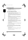
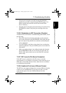
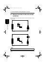
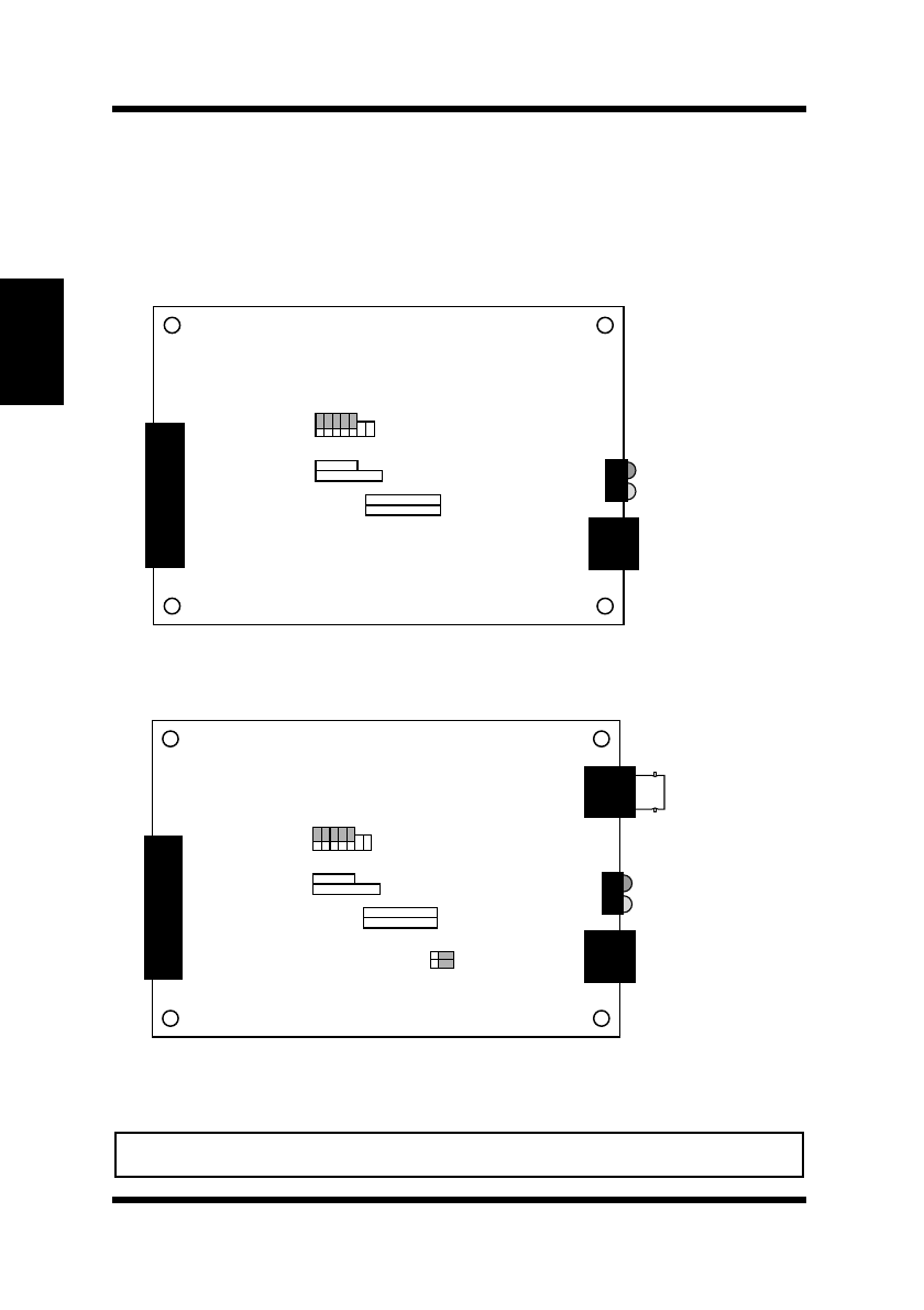
A.1 Network Interface Cards and Jumper Locations
A-2
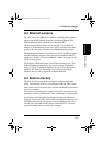
Jumper Settings
Appendix A
A.1 Network Interface Cards and Jumper
Locations
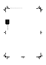
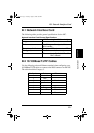
The illustration below shows the location of each of the jumpers on the
Ethernet NIC.
Note
• The shaded areas indicate the default pin positions.
TEST
BYPASS
CUST
P.W.
S.R.
OFF
OFF
OP1
OP6
OP2
OP3
OP4
OP5
OP7
TEST
BYPASS
CUST
P.W.
S.R.
OFF
OFF
THIN 10BT
MAN AUTO
OP1
OP6
JP3
JP4
OP2
OP3
OP4
OP5
OP7
10/100BaseT
10BaseT/2
PageWorks.book Page 2 Tuesday, August 4, 1998 11:21 AM