


12
CONNECTING TO AN AC SOURCE
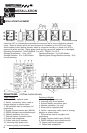
Plug the UPS into a two pole, three wire, grounded receptacle only. Do not use extension
cords, adapter plugs, power strips or surge strips. The MCP 5000iE and MCP 7000iE must
be hardwired (see page 8).
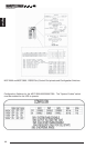
COMPUTER INTERFACE CONNECTION (OPTIONAL)
MINUTEMAN Power Management software and interface cables kits can be used with the
MCP-E units. Use only MINUTEMAN or MINUTEMAN approved interface cables with these
UPS’s. Connect the interface cable to the 9 pin computer interface port on the rear of the
UPS. Secure the connector to the UPS via the screws on the connector housing. Connect
the other end of the cable to the device that will be monitoring/controlling the UPS.
NOTE: Connecting to the computer interface port is optional. The UPS works
properly without this connection.
Plug the equipment into the output receptacles on the back panel of the unit. Do not use
extension cords, adapter plugs, power strips or surge strips. The MCP 5000iE and the MCP
7000iE are hardwire output connections only, be sure the output breaker is in the ON
position. Insure that you do not exceed the maximum output rating of the UPS (refer to the
UPS's back panel or the Electrical Specifications in this manual).
CAUTION!
DO NOT CONNECT A LASER PRINTER TO THE BATTERY BACKUP
RECEPTACLES ON THE UPS UNLESS THE UPS IS RATED 2000VA OR
GREATER. A LASER PRINTER DRAWS SIGNIFICANTLY MORE POWER
WHEN PRINTING THAN AT IDLE, AND MAY OVERLOAD THE UPS.
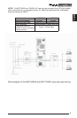
NETWORK SURGE PROTECTION CONNECTION (OPTIONAL)
Connect a 10 Base-T network line to the protection sockets on the rear of the UPS (not
available on all models). This connection will require another length of network cable. The
cable coming from the networked system is connected to the port marked “IN”. The “OUT
port is connected to the equipment to be protected.
NOTE: Connecting to the Network Surge Protection connection is optional. The
UPS works properly without this connection.
CONNECTING YOUR EQUIPMENT
English
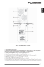
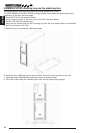
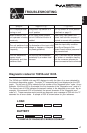
MAINTENANCE BYPASS SWITCH
(Must be performed by Authorized Service Personnel ONLY)
The 5000/7000VA units have a Maintenance Bypass Switch on the rear panel. The
maintenance bypass switch is used to tranfer the utility AC power to the output load without
interrupting the protected equipment, so that general maintenance can be performed. Follow
the steps below to transfer the UPS to the Maintenance Bypass Mode:
1. Turn the Maintenance Bypass Switch to "BPS".
2. Push the ON/OFF button on the front panel.
3. Wait for approximately five minutes before performing any maintenance.
4. The UPS is now ready for general maintenance.
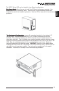
Follow the steps below to switch the UPS back to the Normal On-Line Mode:
1. Push the ON/OFF button on the front panel.
2. Wait for approximately one minute for the inverter to start.
3. Turn the Maintenance Bypass Switch to "UPS".
4. The UPS is now operating in the Normal On-Line Mode.