


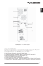

15
English
English
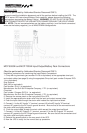
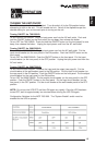
Press and release the main power switch on the front of the unit to turn
on the unit. Press and release again to turn off the unit. Some models
have a circuit breaker on the rear panel that must be turned ON first and
then press the front panel switch to turn the unit ON.
The unit will turn on, perform a self diagnostic test, switch to bypass
mode and then turn on to full inverter mode automatically.
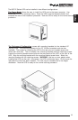
Place your unit in the desired location for use. Connect all equipment power cords to the
receptacles on the rear of the UPS. Please insure you confirm total power requirements
and do not overload the units.
ALARMS
ON BATTERY
When the UPS is operating in the battery mode, the Battery Mode Icon will illuminate and the
audible alarm will sound every 10 seconds. The alarm will stop and the Battery Mode Icon
will extinquish once the UPS returns to AC normal operation.
UPS FAULT
When the UPS detects a fault, the Unit Fault Icon will illuminate and the UPS will emit a
sustained tone. The unit will also display a failure code if available. (see section 5 Trouble-
shooting for failure code definition)
OVERLOAD
When the amount of load attached to the UPS exceeds its power rating, the Unit Overload
Icon will illuminate and the UPS will emit a sustained tone. This alarm will remain on until the
excess load is removed or the UPS’s self protection circuit takes control. If the unit self
protection circuit takes control, the unit will switch to bypass mode until the overload is
removed. If the load is excessive, the input circuit breaker will open and the unit will shut
down.
REPLACE BATTERY
The UPS automatically tests the battery’s condition and will illuminate the Unit Battery Icon
and emit a short beep. This tone will be repeated every hour until the batteries passes a
self test. It is recommended that the UPS be allowed to charge overnight before performing
a battery test to confirm a Weak/Bad Battery condition.
LOW BATTERY WARNING
The UPS will emit two consecutive beeps every five seconds when the battery reserve
runs low. This continues until AC returns or the UPS shuts down from battery exhaustion.
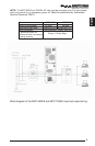
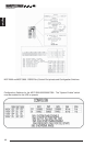
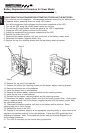
COMMUNICATIONS PORT
Communications port information for 700VA and 1000VA units only:
The communications port is a standard DB9 female with both RS232 and relay contact
closure capability. The units will poll the port and activate the port for RS232 or contact
closure in accordance with the type of cable it finds connected to the port. To change the
port configuration requires the unit be turned off and restarted with the desired cable
connected. The pinout for the port is depicted per the chart below.
Pin 1: Instant off ( pull and hold this pin low to turn off output receptacles)
Pin 2: /TXD
Pin 3: /RXD and receive ups shutdown command
Pin 4: AC fail, NO closes on event
Pin 5: Ground
Pin 6: Low battery warning, NO closes on event
Pin 7: Common return for all relays
Pin 8: Summary alarm, NO closes on AC fail, low battery warning, overload, UPS failure
or unit on bypass
Pin 9: Not Used