


FX2N-32DP-IF Profibus-DP Interface Unit Introduction 1
1-6
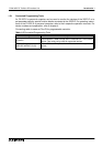
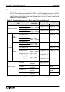
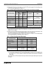
1.3.2 Connected Extension Units/Blocks
The table below shows extension units/blocks and their data lengths when connected to a
32DP-IF. Data is exchanged between the 32DP-IF and DP-master during every cycle. The
maximum amount of data that can be exchanged with the 32DP-IF is 200 bytes of input data
and 200 bytes of output data. Please check the specification of the DP-master, it may limit the
total amount of exchanged data.
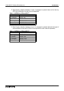
*1 Total 8 bytes, selection between averaged data (BFM #5 ~ #8) or present data (BFM #9 ~
#12) can be done by GSD file configuration for each channel separately.
Table 1.3: Connected Extension Units/Blocks and Exchanged Data Length
Items Description
Exchange Data Length
Output Data (Y) Input Data (X)
Extension I/O Units
FX
2N
-32ER-ES/UL
Input = 16 points
Output = 16 points
2 Bytes (Y0 ~ Y17) 2 Bytes (X0 ~ X17)
FX
2N
-32ET-ESS/UL
FX
2N
-48ER-ES/UL
Input = 24 points
Output = 24 points
3 Bytes (Y0 ~ Y27) 3 Bytes (X0 ~ X27)
FX
2N
-48ET-ESS/UL
Extension
I/O Blocks
FX
2N
Series
FX
2N
-16EX-ES/UL
Input = 16 points
Output = 0 point
- 2 Bytes (X0 ~ X17)
FX
2N
-16EYR-ES/UL
Input = 0 point
Output = 16 points
2 Bytes (Y0 ~ Y17) -FX
2N
-16EYT-ESS/UL
FX
2N
-16EYS-ES/UL
FX
0N
Series
FX
0N
-8EX-UA1/UL
Input = 8 points
Output = 0 point
-
1 Bytes (X0 ~ X7)
FX
0N
-8EX-ES/UL
FX
0N
-16EX-ES/UL
Input = 16 points
Output = 0 point
2 Bytes (X0 ~ X17)
FX
0N
-8ER-ES/UL
Input = 4 points
Output = 4 points
1 Bytes (Y0 ~ Y3) 1 Bytes (X0 ~ X3)
FX
0N
-8EYR-ES/UL
Input = 0 point
Output = 8 points
1 Bytes (Y0 ~ Y7)
-
FX
0N
-8EYT-ESS/UL
FX
0N
-16EYR-ES/UL
Input = 0 point
Output = 16 points
2 Bytes (Y0 ~ Y17)
FX
0N
-16EYT-ESS/UL
Special Function
Blocks
FX
2N
-4DA
Digital to analog
converter
8 Bytes,
Analog output data
(BFM #1 ~ #4)
FX
2N
-4AD
Analog to digital
converter
-
8 Bytes
*1
FX
2N
-4AD-PT
PT100 probe
interface
8 Bytes
*2
FX
2N
-4AD-TC
Thermo-couple
interface
8 Bytes
*3