


FX2N-32DP-IF Profibus Interface unit Appendix A
A-2
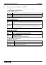
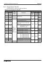
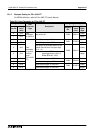
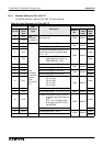
*3 After power on, the default setting of this parameter is 0, as the BFM addresses for read-
ing/writing command are not coded in the parameter data, but are sent together with the
Profibus data. For exchanged data, refer to appendix A-2.
*4 “y” is number of connected special function blocks to 32DP-IF. (y = 1 8)
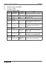
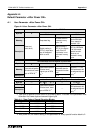
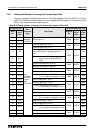
A-2 Exchanged Data by Default Parameter
After power on, the bus node does not know about the I/O features of the connected special
function blocks. So each special function block is assigned to one reading command and one
writing command. The exchanged data is as follows:
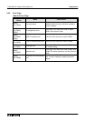
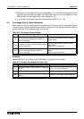
Example
Reading BFM #17 and writing K1000 to BFM #9 in the special function block.
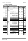
Table A-2: Exchanged Parameter Data
Times Output area (send) Input area (receive)
1st
Special function block’s BFM address is writ-
ten for input data (Reading from 32DP-IF)
(Bit15 = write flag)
This value is BFM’s data read from special
function block.
2nd
This data is written to special function block’s
BFM for output data.
This value was written to special function
block’s BFM.
(Written value is read back)
3rd
Special function block’s BFM address is writ-
ten for output data (writing to 32DP-IF)
(Bit15 = write flag)
This value was special function block’s BFM
address.
(Written value is read back)
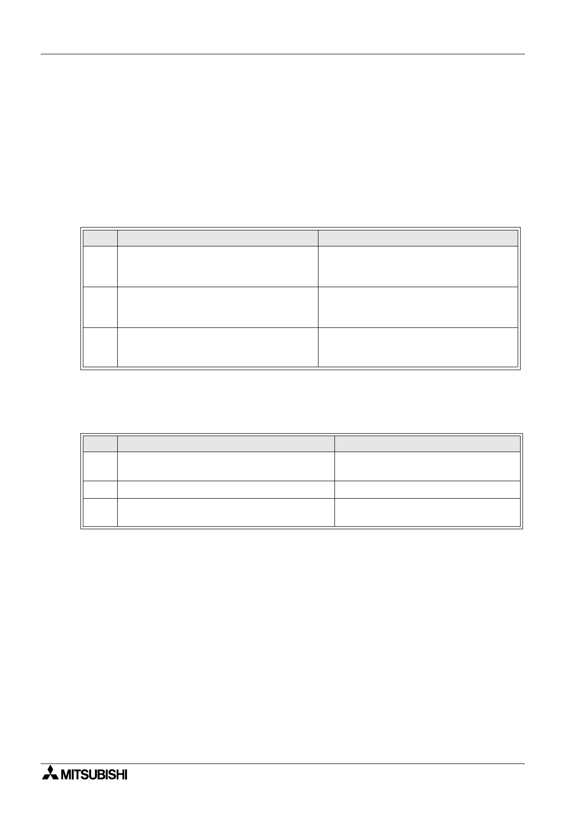
Table A-3: Example Exchanged Parameter Data
Times Output Data Input Data
1st
8011hex = 11hex (17 dez = BFM #17) + 8000 hex
(bit15=1)
nnnn = hex value of BFM #17
2nd 03E8 hex = (1000 dez) 03E8 hex = hex value of BFM #9
3rd
8009 hex = 09 hex (9 dez = BFM #9) + 8000 hex
(bit15=1)
8009 hex = verification of BFM address