


EN-46
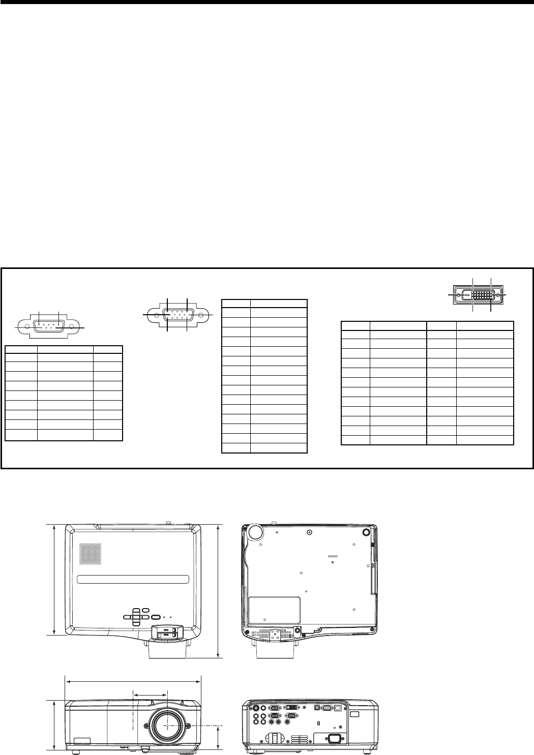
1 R(RED)/CR
2
G(GREEN)/Y
3
B(BLUE)/CB
4 GND
5 GND
6 GND
7 GND
8 GND
9 DDC 5V (*1)
10 GND
11 GND
12 DDC Data (*1)
13 HD/CS
14 VD
15 DDC Clock (*1)
1
-
-
2 TXD IN
3 RXD OUT
4
-
-
5 GND
-
6
-
-
7
-
-
8
-
-
9
-
-
15
11
6
10
15
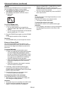
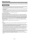
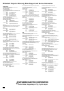
SERIAL (D-SUB 9-pin)
Pin No. Name I/O
COMPUTER/COMPONENT VIDEO IN-1/IN-2
(Mini D-SUB 15-pin)
Pin No. Spec.
DVI-D (HDCP)
(DVI-D 24-pin)
Pin No. Spec. Pin No. Spec.
1 TMDS DATA 2- 13
-
2 TMDS DATA 2+
14 +5V Power
3
TMDS DATA 2 Shield
15 Ground (for +5V)
4
-
16 Hot Plug Detect
5
-
17 TMDS DATA 0-
6 DDC Clock 18 TMDS DATA 0+
7 DDC Data 19
TMDS DATA 0 Shield
8
-
2
0
-
9 TMDS DATA 1- 21
-
10 TMDS DATA 1+ 22
TMDS Clock Shield
11
TMDS DATA 1 Shield
23 TMDS Clock+
12
-
24 TMDS Clock-
1724
16
9
8
1
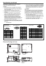
Connectors
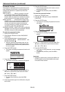
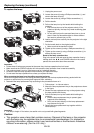
333
59.5
125
84.5
331
272
Dimension Drawings (unit: mm)
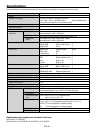
Specifi cations (continued)
15
6
9
(*1 For IN-1 terminal only. )
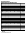
Specifi cation of RGB signals in each computer
mode of the projector (continued)
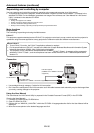
Important:
• Some computers aren’t compatible with the projector.
• The projector’s maximum resolution is 1400 x 1050 pix-
els. It may not display images of higher resolutions than
1400 x 1050 correctly.
• Images with SYNC on G (Green) signal may jitter.
• Images with SYNC on G (Green) signal may be tinged
with green.
•
If the resolution and frequency of your computer aren’
t shown on the table, fi nd the compatible resolution and
frequency by changing the resolution of your computer.
• TV60 and TV50 are equivalent to 480i and 576i
respectively. When these signals are supplied to the
VIDEO IN or S-VIDEO IN terminal, the signal mode is
indicated as TV60 or TV50. When they are supplied to the
COMPUTER IN/COMPONENT VIDEO IN terminals, the
signal mode is indicated as 480i or 576i.
• This projector doesn’t support 480p signals from video
devices having 4 lines (R, G, B, CS*) or having 5 lines (R,
G, B, H, V).
* : Composite Sync
• When a certain signal such as SXGA85 and SXGA85b
is input, the number of displayed colors may decrease
depending on the setting of ASPECT in the FEATURE
menu. Change the signal format of the computer, if
necessary.
REAL mode
When moire patterns or lines of uneven thickness appear
on the projected image, these symptoms may be improved
by displaying it in its original image size (REAL mode). To
display the image in the REAL mode, set ASPECT of the
FEATURE menu to REAL. (See page 23 for menu setting.)
• In the REAL mode, you cannot change the magnifi cation
factor and magnifi cation range.
•
For signals that are larger than the panel resolution, only
their center part is displayed in the REAL mode. The area
exceeding the panel resolution isn
’
t displayed.
• In the REAL mode, images are black-framed when the
image resolution is lower than
1400 x 1050.