


EN-7
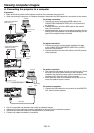
Overview
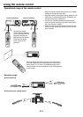
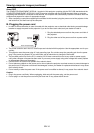
9
7
8
2
1
3
4
5
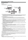
11 101213
6
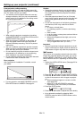
1
2
3
4
5
6789
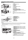
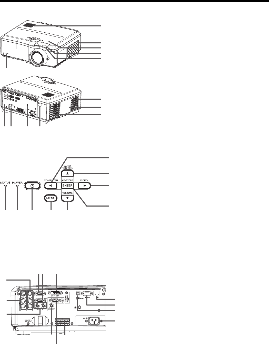
1 Speaker
2 Air inlet grille/Filter cover
3 Control area
4 ZOOM ring
5 FOCUS ring
6 Remote control sensor (Front)
7 Air outlet grille
8 Lamp cover
9 Air outlet grille
10 Remote control sensor (Rear)
11 Kensington Security Lock Standard connector
12 Lock bar (SECURITY ANCHOR)
• Attach a chain, etc. to this lock bar to anchor the projector.
13 Terminal board
Caution:
Do not replace the lamp immediately after using the projector
because the lamp would be extremely hot and it may cause
burns.
Control area
1 COMPUTER/
W
button
2 AUTO POSITION/
S
button
3 VIDEO/
X
button
4 KEYSTONE/ENTER button
5 VOLUME/
T
button
6 MENU button
7 POWER button
8 POWER indicator
9 STATUS indicator
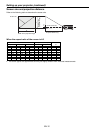
12 3
4
5
6
7
12
13
11
10
9
8
Important:
• While the menu or the screen for the keystone adjustment or password entry is being displayed or image captur-
ing is being executed, the COMPUTER, VIDEO, AUTO POSITION and VOLUME buttons function as the
W
,
X
,
S
and
T
buttons respectively.
• While the menu is on the screen, the KEYSTONE button functions as the ENTER button.
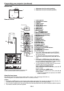
1 COMPUTER/COMPONENT VIDEO IN-1 terminal (Mini
D-SUB 15-pin)
2 COMPUTER/COMPONENT VIDEO IN-2 terminal (Mini
D-SUB 15-pin)
3 COMPUTER/COMPONENT VIDEO DVI-D (HDCP) termi-
nal (DVI-D 24-pin)
4 LAN terminal
5 SERIAL terminal (D-SUB 9-pin)
6 USB (COMPUTER) terminal
7 Power jack
8 Air inlet grille
9 MONITOR OUT terminal (Mini D-SUB 15-pin)
10 AUDIO OUT terminal (Mini jack)
11 AUDIO IN-1 and AUDIO IN-2 terminals (Mini jack)
• The AUDIO IN-1 terminal is used for both COMPUTER 1
and DVI input.
12 S-VIDEO IN terminal and audio input terminals
13 VIDEO IN terminal and audio input terminals
Terminal board
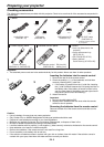
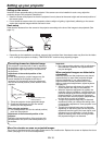
Preparating your projector (continued)